Stay wire binding tool

A technology for drawing wires and tools, which is applied in the field of tools, can solve the problems of waste of iron wire, easy slipping of iron wire, time-consuming and labor-intensive problems, and achieve the effect of high work efficiency, firm and tight winding, and avoiding contact

Active Publication Date: 2013-10-16
STATE GRID CORP OF CHINA +2
View PDF5 Cites 4 Cited by
  • Summary
  • Abstract
  • Description
  • Claims
  • Application Information

AI Technical Summary

Problems solved by technology

The existing method of pulling the wire is time-consuming and laborious. When the force is not enough, the iron wire is easy to slip, and the winding quality is poor. When the force is too large, it is easy to damage the galvanized layer of the iron wire, and the anti-corrosion ability of the iron wire is greatly reduced
In addition, the distance between the curved double-strand cable gradually decreases from top to bottom, so when winding the double-strand cable, it is not easy to determine how far the winding can be stopped, and it is easy to cause waste of iron wire

Method used


Image

  • Stay wire binding tool
  • Stay wire binding tool
  • Stay wire binding tool

Examples


Embodiment 1

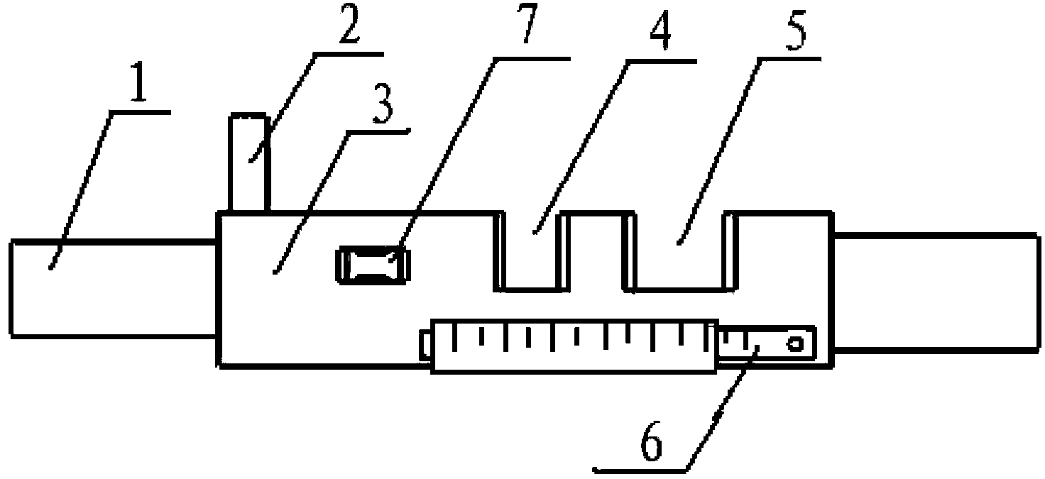
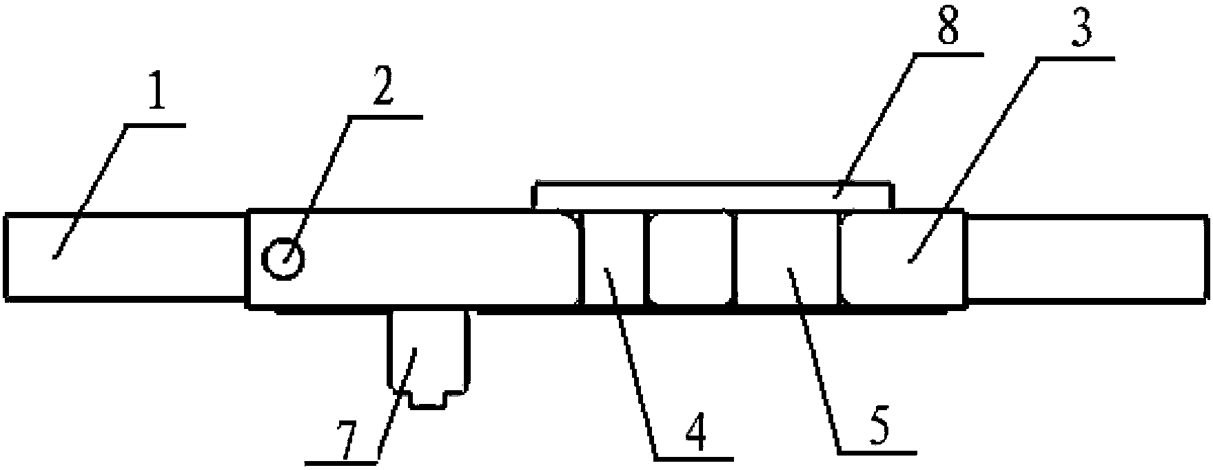
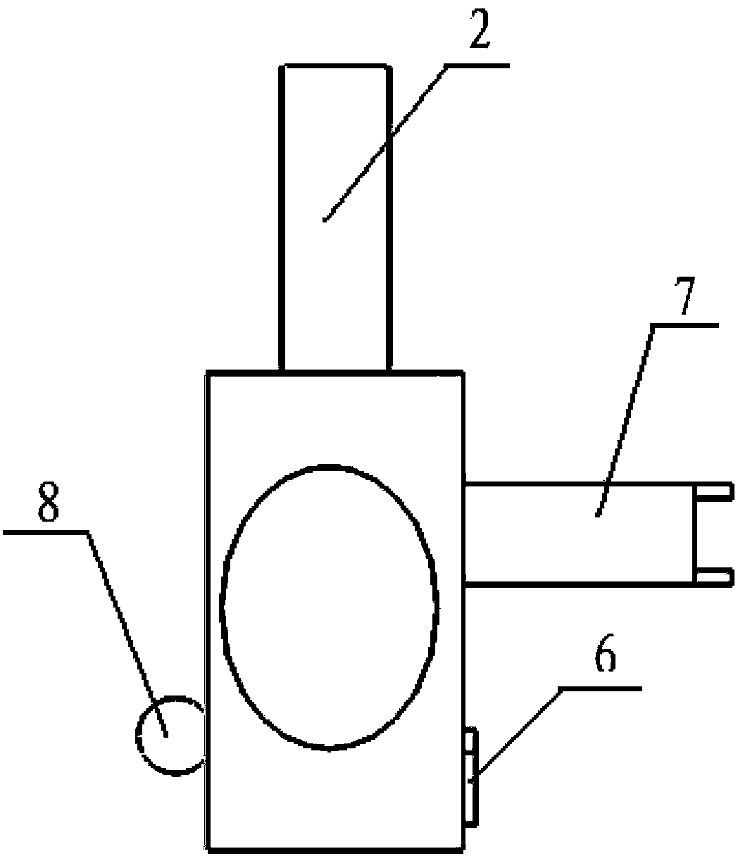
[0023] Pull the wire tool, the structure is as follows figure 1 , figure 2 with image 3 As shown, it includes a strip-shaped insulating board 3, and a handle 1 is fixedly arranged at both ends of the insulating board 3; one end of the side of the insulating board 3 is provided with a hanging wire rod 2, and the hanging wire rod is used for winding and hanging the binding wire. Iron wire, the other end or the middle part of the side of the insulating plate 3 are provided with two wire slots of different widths, and the wire slots are used to block the iron wires. greater than the diameter of the iron wire used; the wire slot is divided into the first wire slot 4 and the second wire slot 5, the width of the first wire slot 4 is smaller than the width of the second wire slot 5, and the first wire slot is located at the second wire slot Two pass through the inner side of the wire trough, the first wire trough is used for winding thinner iron wire, and the second wire trough is...

Embodiment 2

[0030] Pull the line tool, another structure is shown as Figure 4 As shown, the difference with Embodiment 1 is that: the wire groove on the support frame 7 is replaced by a pulley 10, and the pulley 10 is arranged on the upper end of the support rod through a pin; The wheel 9 is hinged at one end of the side of the insulating board 3 through a pin shaft, and the pin shaft is connected perpendicular to the side of the insulating board 3 . Before the pulling wire tool is used, the iron wire of the bundled wire is wound on the winding wheel 9, and the iron wire is output stably through the rotation of the winding wheel during use, and the phenomenon that the iron wire does not shake up and down during the output process makes the The iron wire is wound more stably and compactly on the double-strand stay wire, and the possibility of injury to workers due to the shaking of the iron wire is reduced.


PUM


Abstract

The invention discloses a stay wire binding tool which comprises a strip-shaped insulating board, wherein two handles are fixedly arranged at the two ends of the insulating board respectively; a wire hanging pole used for hanging an iron wire is arranged at one end of the side surface of the insulating board; wire passing grooves with various widths are formed in the other end or the middle part of the insulating board; a support frame used for supporting the iron wire is arranged on the front side of the insulating board between the wire passing grooves and the wire hanging pole; the support frame comprises a support rod perpendicular to the front side of the insulating board; a guide groove used for guiding the iron wire is formed in the upper end of the support rod; an extension scale for measuring the distance and winding length of double stay wires winding the iron wire is hinged to the front side of the insulating board; a metal pole of which the diameter is larger than that of the iron wire in the length direction of the insulating board is fixedly arranged on the back surface of the insulating board. The tool has the characteristics that time and labor are saved; the working efficiency is high; the damage probability of an iron wire galvanized layer is low; the winding degree of the iron wire can be determined.

Description

technical field [0001] The invention relates to a tool for installation and construction of high and low voltage lines, in particular to a tool for pulling wires suitable for binding various electric poles. Background technique [0002] During the construction of the transmission line, the poles in the high and low voltage power supply lines are used to erect the transmission wires. In the fixed installation procedure of the poles, after the poles are erected to the ground, the poles need to be auxiliary fixed with pull wires. When installing the guy wire, one end of the guy wire is first bent and folded in half by the UT clamp to form a double-strand guy wire, and then the overlapping part of the double-strand guy wire is bound with iron wire. This process is called "tying the guy wire". The prior art of backguy is to alternately use multiple portable tools such as vise, wrench, sledgehammer, and galvanized iron wire is wound and bound on double backguy. During the winding...

Claims


Application Information

Patent Timeline
Patent Type & Authority Applications(China)
IPC IPC(8): E04H12/20
Inventor 赵计忠赵英旗曹瑞彬王少波
Owner STATE GRID CORP OF CHINA
Why Eureka
Try Eureka