Railway wagon brake cylinder

A technology for railway freight cars and brake cylinders, which is applied to railway car body parts, pneumatic brakes, brake actuators, etc., can solve the problems of unfavorable grease storage due to the structure of the sealing ring, affecting the performance of grease, and detaching from the piston installation groove, etc. Achieve the effect of avoiding metal surface friction, reducing motion resistance and improving working conditions

Inactive Publication Date: 2013-10-16
MEISHAN CRRC BRAKE SCI & TECH CO LTD
View PDF7 Cites 19 Cited by
  • Summary
  • Abstract
  • Description
  • Claims
  • Application Information

AI Technical Summary

Problems solved by technology

[0003] Leaking brake cylinders were disassembled on site, and it was basically found that the grease in the brake cylinders became thin and black, and naturally flowed to the lower part of the brake cylinder due to gravity and vehicle vibration. There was almost no grease in the upper part, and some scratch marks on the inner wall of the cylinder , In addition, the existing sealing ring structure is not conducive to the preservation of grease, and it is easy to break away from the piston installation groove after oil absorption and expansion, and the sealing belt between the piston and the cylinder body is uneven, resulting in partial wear of the cylinder body, poor dustproof effect, and sand and dust entering the cylinder. Affects grease performance

Method used


Image

  • Railway wagon brake cylinder
  • Railway wagon brake cylinder
  • Railway wagon brake cylinder

Examples


Embodiment Construction

[0027] Below in conjunction with accompanying drawing, the present invention is described in detail.

[0028] In order to make the object, technical solution and advantages of the present invention more clear, the present invention will be further described in detail below in conjunction with the accompanying drawings and embodiments. It should be understood that the specific embodiments described here are only used to explain the present invention, not to limit the present invention.

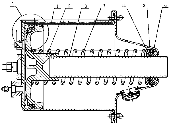
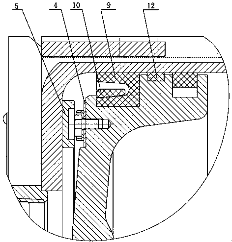
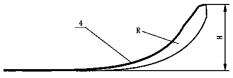
[0029] Such as figure 1 and 2 As shown, a brake cylinder for railway wagons includes a cylinder body 1, a piston assembly 2 and a piston rod 3 arranged in the cylinder body 1, and a cylinder for the piston assembly to rotate when the brake is relieved is arranged in the cylinder body 1. Active lubricating mechanism, the active lubricating mechanism includes a number of spring plates 4 uniformly arranged on the bottom of the piston composition 2, a ring gear seat 5 arranged at the inner bottom...


PUM


Abstract

The invention discloses a railway wagon brake cylinder which comprises a cylinder body, a piston assembly and a piston rod. The piston assembly and the piston rod are arranged in the cylinder body. A drive lubrication mechanism used for enabling the piston assembly to rotate in the process of brake release is arranged in the cylinder body. The drive lubrication mechanism comprises a plurality of leaf springs arranged at the bottom of the piston assembly, a gear ring base arranged at the bottom in the cylinder body, a spring seat arranged at the front end in the cylinder body and a release spring sleeved on the piston rod. The leaf springs are matched with the gear ring base to form a ratchet wheel structure. One end of the release spring abuts against the inner side end face of the piston assembly, the other end of the release spring abuts against the end face of the spring seat, and the release spring is in a compressed state continuously. When brake release is conducted on the piston assembly, the piston assembly can rotate under the action of the drive lubrication mechanism, so that grease naturally flowing to the lower portion of the brake cylinder is guided to the upper portion of the brake cylinder through the rotation of the piston, the grease of the brake cylinder circulates in the brake cylinder, and the function of driving lubrication is achieved.

Description

technical field [0001] The invention relates to a railway wagon brake cylinder with active lubricating function. Background technique [0002] Spinning sealed brake cylinder is a key component of the braking system of railway freight cars, and the fault of brake cylinder is one of the factors that threaten the safety of railway freight cars. In the summer and winter of 2011, the Ministry of Railways organized a research group on the brake system of railway wagons to conduct on-site technical research in the application workshops of some depots in the south and north of my country. The research team inspected a total of 27,600 trucks in summer, and 198 trucks had brake system failures, of which 107 were missing brake cylinders, 38 were leaking brake cylinders, and 3 brake cylinder relief springs were broken, a total of 148 vehicles. Brake cylinder leakage accounted for 19.2% of the faulty vehicles and 0.14% of the total inspected vehicles. The research team inspected about ...

Claims


Application Information

Patent Timeline
Patent Type & Authority Applications(China)
IPC IPC(8): F16D65/14B61H11/06F16D121/04F16D125/08
Inventor 肖晨胡小平李研乐刘毅陈建德安鸿肖维远朱宇
Owner MEISHAN CRRC BRAKE SCI & TECH CO LTD
Why Eureka
Try Eureka