Superconductive heat pipe electric heater

A technology of electric heaters and superconducting tubes, applied in heating methods, indirect heat exchangers, lighting and heating equipment, etc., can solve the problems of slow temperature increase, poor heat dissipation effect, long heating time, etc., to achieve temperature balance, The effect of saving heating time and improving heat transfer efficiency

Active Publication Date: 2013-10-23
山东伟瑞制冷科技有限公司
View PDF5 Cites 17 Cited by
  • Summary
  • Abstract
  • Description
  • Claims
  • Application Information

AI Technical Summary

Problems solved by technology

The above existing electric heater has the following problems due to its own structural characteristics: one, the initial temperature of heat conduction of water, ethanol or heat transfer oil as the heat transfer medium is relatively high, and the corresponding time for heating the heat transfer medium is also relatively short. Long, only when the heat conduction medium itself reaches the heat conduction temperature will it exchange heat with other objects around it, the energy consumption is relatively significant, and the heating time is long, and the temperature rises slowly; second, the heater shell, which is an important part of external heat dissipation And the temperature of the heat dissipation fin itself is low, and it needs to absorb part of the heat transferred by the heat transfer medium. Therefore, the heat dissipated is relatively reduced, and the heat dissipation effect is not good.

Method used


Image

  • Superconductive heat pipe electric heater
  • Superconductive heat pipe electric heater
  • Superconductive heat pipe electric heater

Examples


Embodiment 1

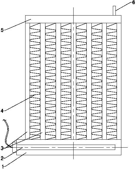
[0026] Refer to attached figure 1 , 2 And 4: The superconducting heat pipe electric heater includes a heater shell 9, an electric heating rod 2 and a heat dissipation fin 4, the heat conduction medium absorbs the heat released by the heating element and dissipates heat to the air through the heat dissipation fin 4, and the heater shell The circulation chamber 5 is installed on the upper part of the body 9, and the heating chamber 1 is installed on the bottom. The circulation chamber 5 and the heating chamber 1 are connected through a plurality of side-by-side heat pipes 3 as heat conduction elements. A circulation channel, the circulation chamber 5, the heating chamber 1 and the heat pipe 3 form a closed vacuum space, the circulation chamber 5, the heating chamber 1 and the heat pipe 3 are filled with heat conduction medium, and the electric heating rod 2 is installed in the heating chamber 1; the heat pipe 3 The inner wall of the heater housing 9 at the rear can also be equi...

Embodiment 2

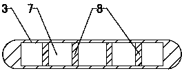
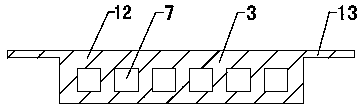
[0033] Refer to attached image 3: the heat pipe 3 is a flat tube with a T-shaped cross section, including a flat tube body 12, a medium circulation channel 7 and cooling fins 13, the flat tube body 12 is provided with a plurality of long strip through holes as the medium circulation channel 7, and the flat tube Radiating fins 13 are arranged symmetrically on both sides of the body 12 . The surface area of ​​the upper and lower sides of the flat tube body 12 is relatively large, and the surface area of ​​the left and right sides is relatively small. The cooling fins 13 are installed symmetrically on the left and right sides. The same plane as an extension of the upper or lower side. The vacuum degree in circulation chamber 5, heating chamber 1 and heat pipe 3 is 10 -3 Pa. When the heat pipe 3 dissipates heat outward, the heat dissipation fins 13 serve as auxiliary heat dissipation parts, effectively increasing the heat dissipation area of ​​the heat pipe 3 and improving the...


PUM


Abstract

The invention provides a superconductive heat pipe electric heater, belongs to the field of electrical heating equipment, and particularly relates to an electric heater using a heat pipe as a heat transfer element to dissipate heat. A heat-conducting medium absorbs heat released by a heating element. The heat is dissipated to the air through fins (4). The superconductive heat pipe electric heater is characterized in that a circulation chamber (5) and a heating chamber (1) are installed in a heater shell body (9); the circulation chamber (5) and the heating chamber (1) are communicated through the heat pipe (3) which is used as a heat conduction element; the circulation chamber (5), the heating chamber (1) and the heat pipe (3) form an airtight vacuum space; the circulation chamber (5), the heating chamber (1) and the heat pipe (3) are filled with heat-conducting media respectively; an electrical heating rod (2) is installed in the heating chamber (1). According to the superconductive heat pipe electric heater, the heating method and heat conduction method of a traditional electric heater are changed, superconductive liquid is used as the heat-conducting media, therefore, the temperature rise speed is increased, energy sources are saved, and heat exchange efficiency is improved at the same time.

Description

technical field [0001] A superconducting heat pipe electric heater belongs to the field of electric heating equipment, and specifically relates to an electric heater which utilizes a heat pipe as a heat transfer element to dissipate heat. Background technique [0002] At present, most of the existing electric heaters include structures such as a heater shell, a heating element, a heat conduction medium, and heat dissipation fins. Most of the heat conduction mediums are water, ethanol or heat conduction oil, etc. In order to heat the heat conduction medium through the heating element after electrification, the heat transfer is realized through the heat exchange between the heat conduction medium itself and the heater shell, and finally the heat is dissipated through the heater shell. The above existing electric heater has the following problems due to its own structural characteristics: one, the initial temperature of heat conduction of water, ethanol or heat transfer oil...

Claims


Application Information

Patent Timeline
Patent Type & Authority Applications(China)
IPC IPC(8): F24D13/04F28D15/02
Inventor 丁伟蔡莹何建洋
Owner 山东伟瑞制冷科技有限公司
Why Eureka
Try Eureka