Method for performing pressure fluctuation calibration on differential pressure transducer
A differential pressure sensor, sensor technology, applied in the direction of measuring fluid pressure, instruments, measuring devices, etc., can solve the problems of reducing friction coefficient, high cost, many auxiliary equipment, etc., to achieve high pressure measurement resolution, accurate pressure change, The effect of reducing the cost of the installation
- Summary
- Abstract
- Description
- Claims
- Application Information
AI Technical Summary
Problems solved by technology
Method used
Image
Examples
Embodiment 1
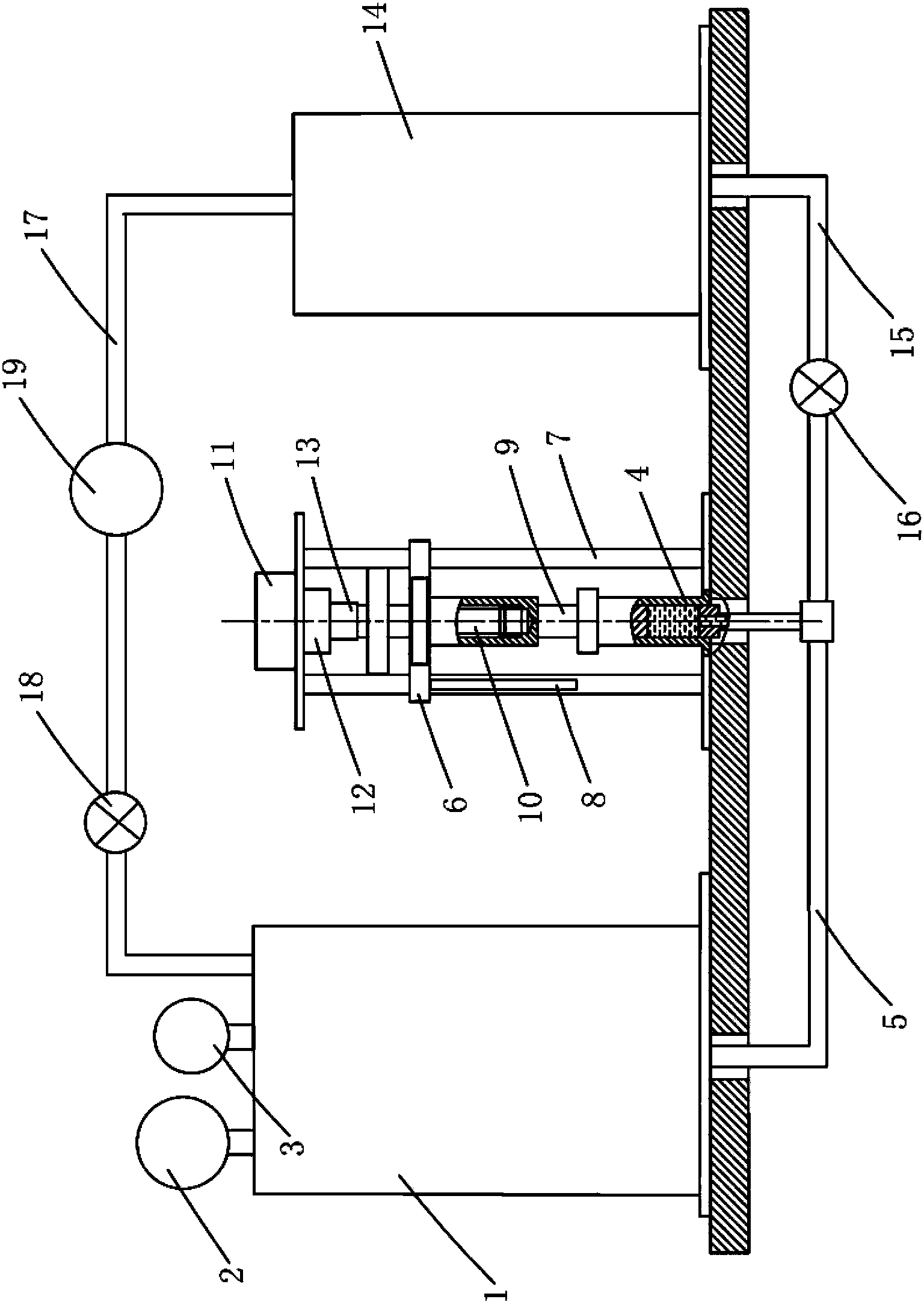
[0027] Embodiment 1: see figure 1 , to calibrate the pressure fluctuation of the pressure sensor, the device includes:
[0028] The main pressure vessel 1 and the standard pressure sensor 2 connected to the main pressure vessel and the pressure sensor 3 to be calibrated;
[0029] The frame and the cylinder body 4 fixed on the frame, the bottom of the inner cavity of the cylinder body 4 communicates with the main pressure vessel 1 through the No. Between the seals, the piston moves up and down to drive the fluid level in the cylinder cavity to rise and fall, causing the fluid pressure in the main pressure vessel to fluctuate. The top outer wall of the piston rod 9 of the piston is fixed on a guide flange 6, and the guide flange 6 takes the column 7 of the frame as a guide rail, and is provided with a displacement sensor 8 on the guide flange, and the upper section of the piston rod 9 is hollow. And be provided with internal thread, the top of frame is provided with lead screw...
Embodiment 2
[0035] Embodiment 2: For the pressure fluctuation calibration of the differential pressure sensor, its device includes:
[0036] The main pressure vessel 1 and the standard pressure sensor 2 connected to the main pressure vessel and the pressure sensor 3 to be calibrated;
[0037] The frame and the cylinder body 4 fixed on the frame, the bottom of the inner cavity of the cylinder body 4 communicates with the main pressure vessel 1 through the No. Between the seals, the piston moves up and down to drive the fluid level in the cylinder cavity to rise and fall, causing the fluid pressure in the main pressure vessel to fluctuate. The top outer wall of the piston rod 9 of the piston is fixed on a guide flange 6, and the guide flange 6 takes the column 7 of the frame as a guide rail, and is provided with a displacement sensor 8 on the guide flange, and the upper section of the piston rod 9 is hollow. And be provided with internal thread, the top of frame is provided with lead screw...
PUM
 Abstract
Description
Claims
Application Information
 - R&D
- Intellectual Property
- Life Sciences
- Materials
- Tech Scout
- Unparalleled Data Quality
- Higher Quality Content
- 60% Fewer Hallucinations
Browse by: Latest US Patents, China's latest patents, Technical Efficacy Thesaurus, Application Domain, Technology Topic, Popular Technical Reports.
© 2025 PatSnap. All rights reserved.Legal|Privacy policy|Modern Slavery Act Transparency Statement|Sitemap|About US| Contact US: help@patsnap.com

