
Adjustable weld inspection guided wave probe and use method thereof

An adjustable and receiving probe technology, which is applied in the field of guided wave probes for ultrasonic detection of weld defects and probes for non-destructive testing of welds. The effect of reducing the detection blind area, improving the detection accuracy and convenient operation

Active Publication Date: 2013-10-23
江苏省特种设备安全监督检验研究院镇江分院 +1
View PDF8 Cites 9 Cited by
  • Summary
  • Abstract
  • Description
  • Claims
  • Application Information

AI Technical Summary

Problems solved by technology

The existing ultrasonic testing method can only carry out the inspection with the guided wave probe, which cannot reliably fix the guided wave probe on the weld, which affects the accuracy of the detection, and cannot be well adapted to the flaw detection of welds with different widths.

Method used


Image

  • Adjustable weld inspection guided wave probe and use method thereof
  • Adjustable weld inspection guided wave probe and use method thereof
  • Adjustable weld inspection guided wave probe and use method thereof

Examples


Embodiment 1

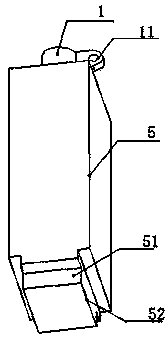
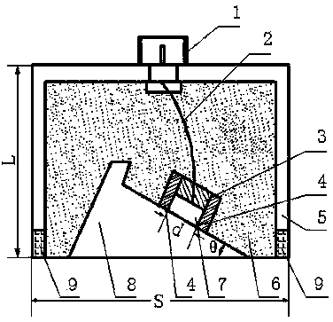
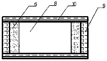
[0035] The transmitting probe and receiving probe articulated by the detachable hinge 11 are horizontally arranged side by side with an adjustable angle, and the surface of the weld 21 to be inspected connecting two metal plates 20 is coated with a viscous couplant, and the transmitting probe and receiving probe respectively pass through the strip at the bottom. The magnets 9 are laterally side by side and adsorbed and fixed on the weld seam to be inspected. By accurately adjusting the included angle α between the transmitting probe and the receiving probe, which is less than or equal to 15°, the best coupling between the wider weld seam 21 and the transmitting probe and the receiving probe can be realized.

Embodiment 2

[0037]The transmitting probe and the receiving probe are arranged longitudinally front and back, the surface of the weld 21 to be inspected connecting two metal plates 20 is coated with a viscous couplant, and the two adjustable guided wave probes for weld seam flaw detection are respectively adsorbed longitudinally front and back by the strip magnet 9 at the bottom It is fixed on the weld seam 21 to be inspected. This allows an optimal coupling to the invention for narrower welds.


PUM

PropertyMeasurementUnit
frequencyaaaaaaaaaa

Abstract

The invention discloses an adjustable weld inspection guided wave probe and a use method of the adjustable weld inspection guided wave probe. The adjustable weld inspection guided wave probe comprises a detachable hinge between upper ends of a transmitting probe and a receiving probe, bar-shaped magnets at two sides of the bottom surface of a metal housing along the width direction, flexible sound insulation strips at two sides of the bottom of the probe along the length direction, and a wedge made of a polyurethane material with excellent wear resistance, flexibility and sound permeability, wherein the detachable hinge can be used for adjusting an included angle between the transmitting probe and the receiving probe and enabling the transmitting probe and the receiving probe to be transversely arranged on a wider weld in parallel or enabling the transmitting probe and the receiving probe to be arranged on a narrower weld along the longitudinal direction of the weld front and back so that the transmitting probe, the receiving probe and the weld are optimally coupled. The flexible wedge can be used for enabling a larger coupling surface to be available between the probes and the weld, and the bar-shaped magnets are attracted on the weld for being coupled and fixed, thus a stable echo signal with less clutters is obtained. The adjustable weld inspection guided wave probe is simple in structure and convenient and flexible to use and operate, and is improved in detection accuracy.

Description

technical field [0001] The invention relates to a probe for nondestructive testing of welds, in particular to a guided wave probe for ultrasonic testing of weld defects, which belongs to the technical field of nondestructive testing. Background technique [0002] Welding is a metal fixed connection process that fuses the connecting edges of two metal materials at high temperature so that the two metal materials are fixedly connected to each other. Due to the influence of various factors, welding defects such as cracks, incomplete fusion, pores, and undercuts often appear at welds. Some important welded structural parts such as ship hulls, pressure vessels, pipelines and load-bearing structural parts of important equipment, etc. If there are the aforementioned welding defects, there will be major safety hazards such as weld cracking and structural component failure. Therefore, in the manufacturing process of welded structural parts, a certain number of ultrasonic or radiogr...

Claims


Application Information

Patent Timeline
Patent Type & Authority Applications(China)
IPC IPC(8): G01N29/24
Inventor 严有琪郭子青许桢英雷玉兰高书苑杨川张晴
Owner 江苏省特种设备安全监督检验研究院镇江分院
Learn More