Adjusting mechanism of diaphragm plate of alignment system

A technology for adjusting mechanisms and aligning systems, applied in optics, microlithography exposure equipment, and photoplate-making processes on patterned surfaces, etc., can solve problems such as poor processing technology, inconvenient operation, and increased difficulty, and achieve simplification structure, improving convenience and reducing processing difficulty

Active Publication Date: 2013-10-23
SHANGHAI MICRO ELECTRONICS EQUIP (GRP) CO LTD
View PDF5 Cites 8 Cited by
  • Summary
  • Abstract
  • Description
  • Claims
  • Application Information

AI Technical Summary

Problems solved by technology

[0006] However, the above structure has the following problems: figure 2 The dimensional accuracy of the diaphragm plate shown is high, and its structure is poor in processability. The middle part of the diaphragm plate is a cylindrical protrusion that can be rotated relatively and the protrusions on the upper part are set for adjusting Rz, which increases the mechanical processing. Difficulty, due to the need for milling, the parts of the square holes that act as apertures in the figure cannot be processed too thin, but from the functional requirements, the thinner the structure of this part, the better; figure 1 The parts shown are initially connected to the OM housing and then fixed to each other after adjustment. When the aperture plate fixing screw 102 is tightened to fix the aperture plate 101 to the aperture support plate 103, the space is very limited and the operation is very inconvenient.

Method used


Image

  • Adjusting mechanism of diaphragm plate of alignment system
  • Adjusting mechanism of diaphragm plate of alignment system
  • Adjusting mechanism of diaphragm plate of alignment system

Examples


Embodiment Construction

[0024] In order to better understand the technical content of the present invention, specific embodiments are given together with the attached drawings for description as follows.

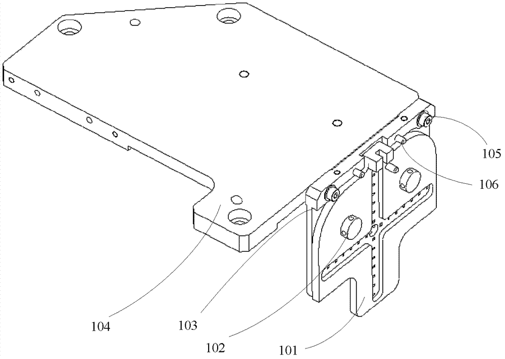
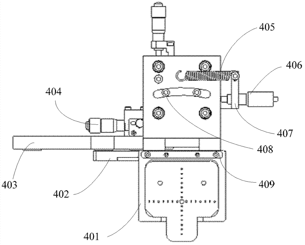
[0025] Please refer to image 3 and Figure 4 , image 3 and Figure 4 Shown is a schematic structural diagram of the adjustment mechanism of the aperture plate of the alignment system in a preferred embodiment of the present invention. The present invention proposes an adjustment mechanism for the aperture plate of the alignment system, which includes: an operating machine housing; an aperture plate fixing plate 402 fixed on the operating machine housing; a sliding table fixing plate 403 fixed on the The XY slide table 404 is fixed on the slide table fixing plate 403, the slide table connecting plate 410 is installed on the XY slide table 404, and the XY slide table 404 has a knob to control the slide table. The table connecting plate 410 moves independently in the X and Y directions relative ...


PUM


Abstract

The invention provides an adjusting mechanism of a diaphragm plate of an alignment system. The adjusting mechanism comprises an operation cabinet shell, a diaphragm plate fixing board, a sliding table fixing board and an Rz adjusting board, wherein the diaphragm plate fixing board and the sliding table fixing board are fixed on the operation cabinet shell, an XY sliding table is fixed on the sliding table fixing board, a sliding table connecting board is installed on the XY sliding table which is provided with a knob for controlling the sliding table connecting board to independently move in the X direction and the Y direction relative to the operation cabinet shell, the Rz adjusting board is provided with an arc track hole and is matched with guide pins which are arranged on the sliding table connecting board, the Rz adjusting board can slide in a track along the guide pins, i.e., the Rz adjusting board can rotate in the Rz direction relative to the sliding table connecting board, and a diaphragm plate assembly is fixed on the diaphragm plate fixing board. According to the adjusting mechanism of the diaphragm plate of the alignment system, three-degree-freedom independent adjustment on the diaphragm plate can be realized, and the convenience of the adjustment and the structure stability can be improved.

Description

technical field [0001] The invention relates to the field of alignment systems for silicon wafers of photolithography machines, and in particular to an adjustment mechanism for an alignment system aperture plate. Background technique [0002] The silicon wafer alignment system is the key subsystem of the lithography machine. In the current off-axis alignment technology, the full-field alignment mark or scribe line alignment mark located in the non-exposed area of ​​the silicon wafer is passed through a The set of optical systems is imaged onto the reference plate as a position reference, and the position of the silicon wafer alignment mark is obtained by determining the deviation of the aerial image of the alignment mark relative to the reference mark on the reference plate. [0003] The entire alignment optical system is a 4F system, the alignment mark is located on the front focal plane of the front lens group, and the reference grating is located on the rear focal plane o...

Claims


Application Information

Patent Timeline
Patent Type & Authority Applications(China)
IPC IPC(8): G03F9/00G03F7/20
Inventor 袁永刚
Owner SHANGHAI MICRO ELECTRONICS EQUIP (GRP) CO LTD
Why Eureka
Try Eureka