Photoelectric composite cable

A photoelectric composite and cable technology, applied in communication cables, cables, optics, etc., can solve the problems of increased signal transmission loss, large cable diameter, and increased cable bending rigidity, so as to suppress the application of external force and achieve smooth wiring. , the effect of good transmission characteristics

Inactive Publication Date: 2013-10-23
SUMITOMO ELECTRIC IND LTD
View PDF5 Cites 2 Cited by
  • Summary
  • Abstract
  • Description
  • Claims
  • Application Information

AI Technical Summary

Problems solved by technology

[0005] However, if the wires arranged on the outer periphery of the optical fiber are twisted pairs or quadruple twisted wires, the diameter of the cables will become larger, making it difficult to smoothly route them to narrow spaces, etc.
In addition, a cable in which electric wires such as twisted wires are arranged skewed in the circumferential direction may have higher bending rigidity than a cable in which electric wires are uniformly arranged in the circumferential direction. S-type case
In this case, the transmission loss of the signal transmitted by the optical fiber increases

Method used


Image

  • Photoelectric composite cable
  • Photoelectric composite cable
  • Photoelectric composite cable

Examples


Embodiment Construction

[0020] Hereinafter, an example of an embodiment of the photoelectric composite cable according to the present invention will be described with reference to the drawings.

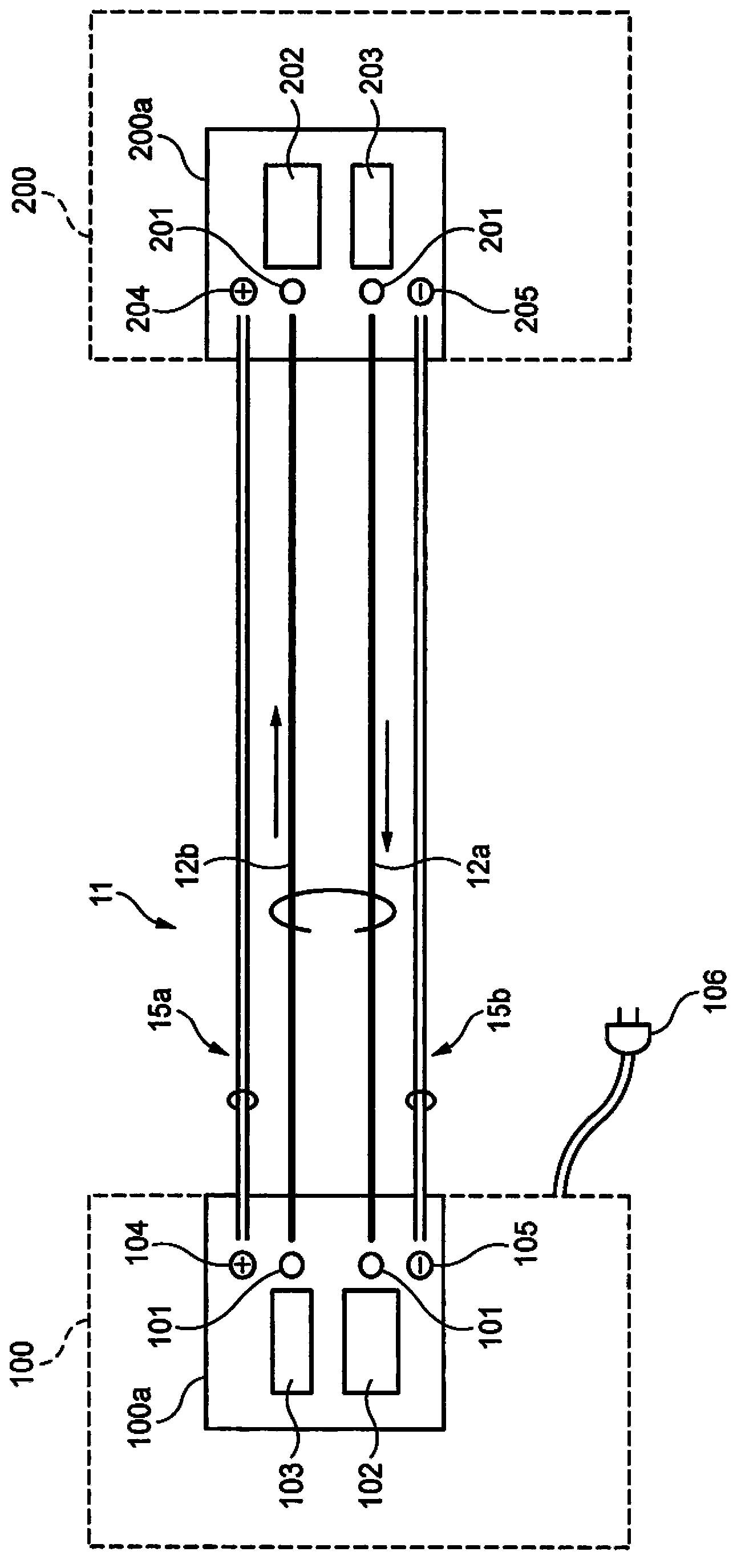
[0021] figure 1 It is a schematic diagram for explaining a state in which the personal computer 100 and the power supply hard disk 200 are electrically and optically connected through the photoelectric composite cable 11 as an example of using the photoelectric composite cable 11 . Such as figure 1 As shown, the photoelectric composite cable 11 connects the personal computer side connector 100a (an example of a connector) and the hard disk side connector 200a (an example of a connector), wherein the personal computer side connector 100a and the personal computer 100 The cable connection portion is connected, and the hard disk side connector 200 a is connected to the cable connection portion of the power supply type hard disk 200 .

[0022] The connector 100a on the personal computer side has: a light recei...


PUM

PropertyMeasurementUnit
diameteraaaaaaaaaa
elastic modulusaaaaaaaaaa

Abstract

The photoelectric composite cable 11 includes: an optical fiber 12; and a plurality of three or more electric wires 15, wherein, in a case where a cross-section of the photoelectric composite cable is viewed in a direction perpendicular to the cross-section, the plurality of electric wires 15 are each independently arranged on a circumference of a periphery of the optical fiber 12. The photoelectric composite cable 11 can be smoothly wired in a narrow space or the like while maintaining good transmission characteristics of optical fibers 12 by suppressing the optical fibers 12 from being applied with an external force without an increase in the diameter of the cable 11.

Description

technical field [0001] The invention relates to a photoelectric composite cable with electric wires and optical fibers. Background technique [0002] For medical equipment, video cameras, personal computers and their peripherals, high-speed communication is required along with further enhancement of functions. Therefore, a photoelectric composite cable combining electric wires and optical fibers is used. [0003] As a photoelectric composite cable, the following technology is known: a plurality of optical fibers are arranged at intervals on the outer periphery of the core material, and a partition plate for covering the core material and the optical fibers is provided on the outside of the core material. Four-core twisted electric wires are arranged at positions corresponding to the distance between the optical fibers, and a sheath is provided on the outside of the electric wires (for example, refer to Patent Document 1). [0004] Patent Document 1: Japanese Publication No...

Claims


Application Information

Patent Timeline
Patent Type & Authority Applications(China)
IPC IPC(8): H01B11/22
CPCG02B6/4416H01R3/00H01B11/22
Inventor 坂部至本间祐也关口知树荒生肇林下达则
Owner SUMITOMO ELECTRIC IND LTD
Why Eureka
Try Eureka