Power connector assembly and adapter plug

A power connector and combination structure technology, which is applied in the direction of connection, two-pole connection, two-part connection device, etc., can solve the problems of lack of applicability, complex structure of power plug and adapter plug, time-consuming manufacturing process of power plug and adapter plug, etc. question

Inactive Publication Date: 2013-10-23
DELTA ELECTRONICS (THAILAND) PUBLIC CO LTD
View PDF4 Cites 6 Cited by
  • Summary
  • Abstract
  • Description
  • Claims
  • Application Information

AI Technical Summary

Problems solved by technology

In short, the shells of the power plug and the adapter plug are provided with matching fastener structures, which will make the structure of the power plug and the adapter plug more complicated, and the power plug and the adapter plug need to be molded separately.
In other words, the manufacturing process of the power plug and the adapter plug is more time-consuming and its manufacturing cost will also increase
In addition, the power plug and the adapter plug with a special fastener structure can only be mated and combined with each other, and different plugs cannot be arbitrarily converted to meet the needs of different countries.
When the user travels in different countries, he still needs to carry the power plug and the adapter plug with the special fastener structure at the same time. In other words, carrying the power plug and the adapter plug with the special fastener structure at the same time will cause the use Inconvenience and confusion for users, and lack of applicability

Method used


Image

  • Power connector assembly and adapter plug
  • Power connector assembly and adapter plug
  • Power connector assembly and adapter plug

Examples


Embodiment Construction

[0048] Some typical embodiments embodying the features and advantages of the present invention will be described in detail in the description in the following paragraphs. It should be understood that the present invention is capable of various changes in different forms without departing from the scope of the present invention, and that the description and drawings are illustrative in nature and are not intended to limit the present invention.

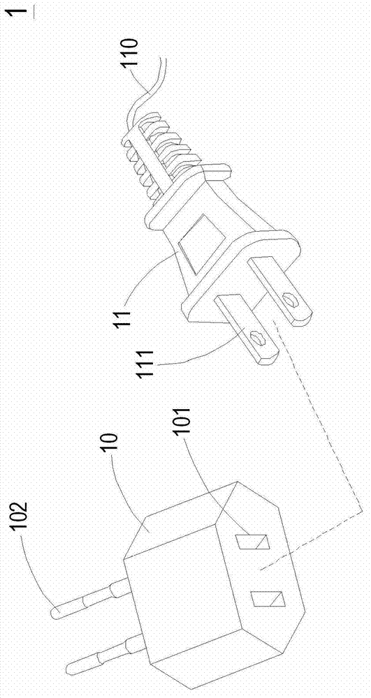
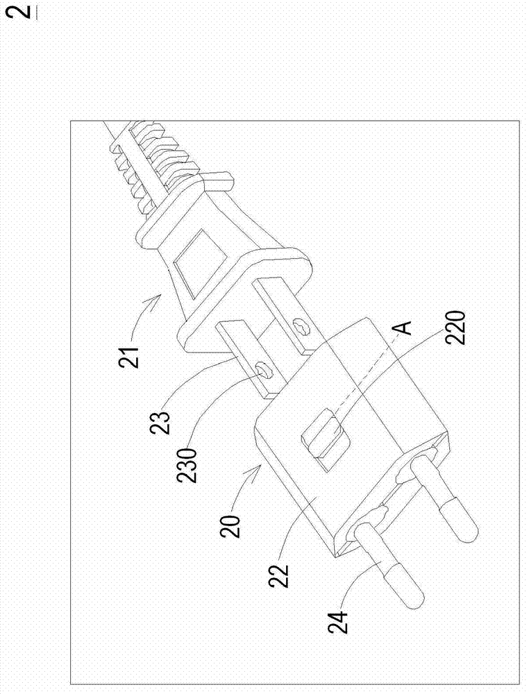
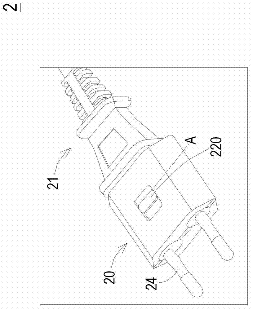
[0049] Figure 2A It is a schematic structural diagram of the combined structure of the power connector in a preferred embodiment of the present invention before it is assembled. Such as Figure 2A As shown, the power connector combination structure 2 of the present invention includes a power plug 21 (or called a power cord plug) and an adapter plug 20 , wherein the power plug 21 has at least two first conductive terminals 23 . For example, the power plug 21 can be a two-pin flat plug conforming to Taiwan regulations and American reg...


PUM


Abstract

A power connector assembly (2) includes an appliance plug (21) and an adapter plug (20). The appliance plug (21) has at two first contact terminals (23), wherein each of the first contact terminals (23) has a perforation (230). The adapter plug (20) includes a casing (22), a switching element (220), at least two second contact terminals (201), and at least two locking elements (202). Each of the locking elements (202) has a protrusion part (202c). When the switching element (220) is located at a first position (A), the protrusion part (202c) of the locking element (202) is accommodated within the perforation (230) of the corresponding first contact terminal (23), so that the locking element (202) is in a locked state. In the locked state, the first contact terminal (23) and the corresponding locking element (202) are coupled with each other and the first contact terminal (23) and the corresponding second contact terminal (201) are electrically connected with each other.

Description

technical field [0001] The invention relates to a combined structure of a power connector, in particular to a combined structure of a power connector of a power plug and an adapter plug. The invention also relates to an adapter plug with a locking mechanism. Background technique [0002] With the advancement of technology, power converters, such as power adapters or chargers, have become indispensable electronic devices for various electrical equipment. For example, the mains power can be rectified and converted into DC by using the power adapter to supply power to a powered device, such as a notebook computer. In addition, the DC power converted by the charger can be used to charge a rechargeable battery of a powered device, such as a mobile phone or a digital camera. [0003] Generally speaking, the power converter includes a power plug for plugging into a power socket to receive commercial power. Due to the development of international business and more and more attent...

Claims


Application Information

Patent Timeline
Patent Type & Authority Applications(China)
IPC IPC(8): H01R13/627H01R13/629H01R24/00H01R31/06
CPCH01R31/06H01R2103/00H01R24/28H01R13/707
Inventor 厄特达宾·宏殷黄瑞庆
Owner DELTA ELECTRONICS (THAILAND) PUBLIC CO LTD
Why Eureka
Try Eureka