Fast clamp with moving grip
A technology of movable collets and collets, which is applied in the direction of clamps, manufacturing tools, etc., can solve the problems of increasing the cost of use, achieve the effect of reducing labor intensity, reducing strength, and improving the scope of application
- Summary
- Abstract
- Description
- Claims
- Application Information
AI Technical Summary
Problems solved by technology
Method used
Image

Examples
Embodiment Construction
[0022] The preferred embodiments of the present invention will be described in detail below in conjunction with the accompanying drawings, so that the advantages and features of the present invention can be more easily understood by those skilled in the art, so as to define the protection scope of the present invention more clearly.
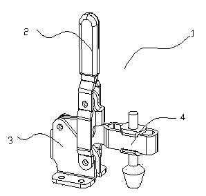
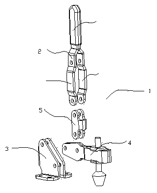
[0023] The invention provides a quick tong with a movable chuck and a power assist device which can effectively relieve the labor intensity of the user.
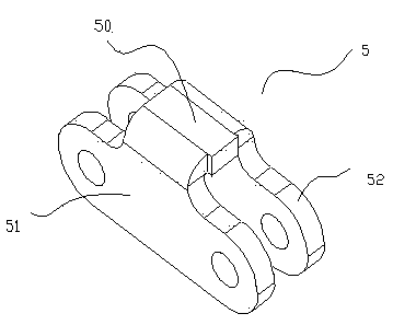
[0024] Such as Figure 1 to Figure 4 As shown, a quick clamp 1 with a movable chuck includes a manual part 2, a base 3 and a chuck 4, a connecting ring block 5 is arranged between the manual part 2 and the base 3, and the connecting ring block 5 is connected by a pin It is movably connected with the manual part 2 and the chuck 4 .
[0025] The connecting ring block 5 includes a middle part 50, a first wing part 51 and a second wing part 52 connected to the middle part 50, and the first wing pa...
PUM
 Abstract
Description
Claims
Application Information
PatSnap Eureka turns technology decisions into work you can execute. Powered by our Innovation Knowledge Graph, it runs expert workflows across engineering, life sciences, materials and intellectual property. Get your review-ready output in minutes.


