Vane machine with axial and radial inlet/outlet

A mechanical and inlet technology, applied in the field of wing core machinery, can solve problems such as the limitation of the area and size of the outlet, and achieve the effects of enlarging the cross-sectional area, reducing the flow rate, and reducing the cost.

Inactive Publication Date: 2013-10-30
ROBERT BOSCH GMBH
View PDF5 Cites 0 Cited by
  • Summary
  • Abstract
  • Description
  • Claims
  • Application Information

AI Technical Summary

Problems solved by technology

[0004] A disadvantage of the known wing core machine is that the area of ​​the axial inlet and the axial outlet is limited by the size of the rotor

Method used


Image

  • Vane machine with axial and radial inlet/outlet
  • Vane machine with axial and radial inlet/outlet
  • Vane machine with axial and radial inlet/outlet

Examples


Embodiment Construction

[0023] figure 1 Shown without control parts (in image 3 The perspective view in the case of reference number 70 ), so that the first rotor 32 can be seen. exist figure 2 relative to figure 1 Only the viewing direction is changed so that the second rotor 33 can be seen.

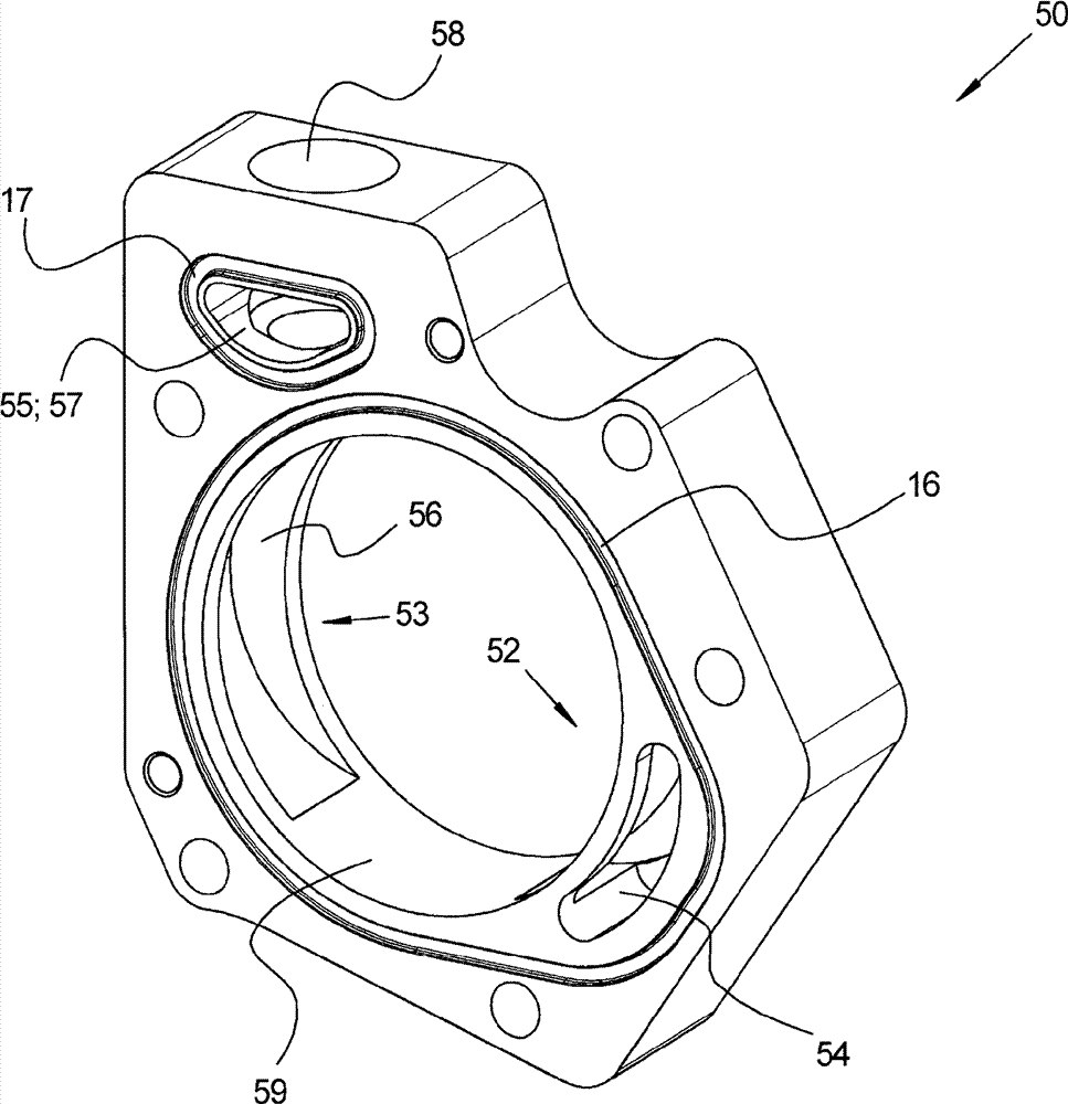
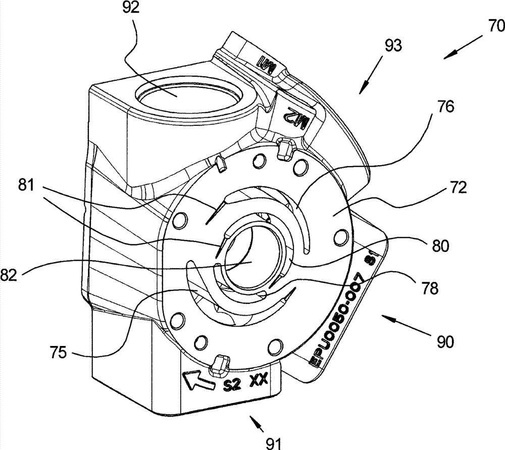
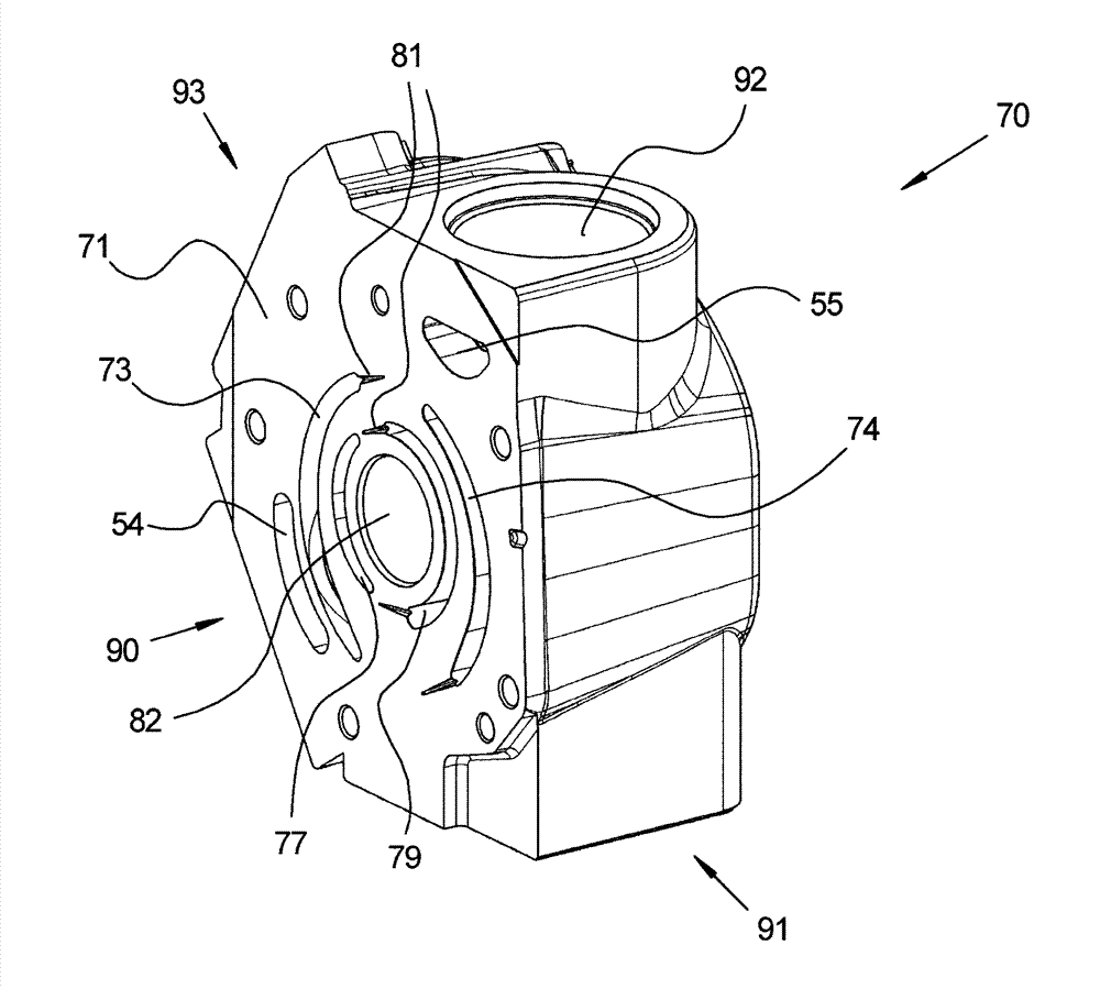
[0024] Described wing core machine 10 comprises housing 11, and this housing then comprises first locking plate 13, first cam part 50, control part (in image 3 Middle number 70), the second cam member 51 and the second lock plate 14 . The locking plate 13; 14 and the associated cam part 50; 51 are fixed on the control part with bolts 12.

[0025] A rotor shaft 30 is rotatably mounted in the housing 11 , protruding from the housing 11 with a drive journal 36 so that it can be brought into a rotational drive connection, for example, with an electric motor. . The swivel bearing is here in the control plate and is preferably designed in the form of a hydrodynamic slide bearing. The first locking plate 1...


PUM


Abstract

The invention relates to a vane machine with an axial and radial inlet/outlet, and particularly provides a vane machine (10) comprising a housing (11) and one or two rotors (32, 33) rotatably mounted in the housing (11) with respect to an axis (31). The rotors (32, 33) have radially movable vanes (34), wherein each rotor is enclosed by an associated cam (50) matched with the rotor (32, 33). The vanes (34) abut against the associated flat contact surface of a control part together with the rotors and the cams, wherein an axial inlet and an axial outlet are arranged on the abutment surface and within the associated cam (50). According to the invention, the cams (50) and associated vanes (34) are arranged opposite to each other, wherein at least one radial inlet and at least one radial outlet (52, 53) are provided. The radial inlet and the radial outlet are arranged in fluid communication with each other through an associated inlet connection channel and an outlet connection channel (54, 55).

Description

technical field [0001] The invention relates to a wing core machine according to the preamble of claim 1 . Background technique [0002] A wing core machine is known from DE 44 14 913 C2. The wing core mechanism includes a housing with control and cam components. In the housing, a rotor with radially movable vanes is supported rotatably about an axis of rotation. The rotor with wings and the cam part bear sealingly against an associated flat contact surface of the control part. An axial inlet and an axial outlet are arranged in the control part, and the axial inlet and the axial outlet are arranged inside the cam part. Since the inlet and outlet are arranged in a single control element, this wing core machine has a small axial overall length. [0003] It should be noted that the wing core machine according to the invention can be operated not only as a pump but also as a motor. Furthermore, the wing core machine according to the invention can optionally be equipped with...

Claims


Application Information

Patent Timeline
Patent Type & Authority Applications(China)
IPC IPC(8): F01C21/18F01C21/00
CPCF04C2/344F01C21/10F04C2/3441F04C15/06F04C18/3442F04C2250/10
Inventor M.昂格
Owner ROBERT BOSCH GMBH
Why Eureka
Try Eureka