Exhaust gas reducing apparatus

A technology of exhaust gas and exhaust gas filter, which is applied in the direction of exhaust device, silencer device, exhaust treatment, etc. It can solve the problems of unstable flame, difficult flame, difficult to effectively remove filter soot particles, etc., so as to ensure a stable rise Or be able to maintain and remove the effect of soot

Active Publication Date: 2013-10-30
CLEANEARTH
View PDF7 Cites 4 Cited by
  • Summary
  • Abstract
  • Description
  • Claims
  • Application Information

AI Technical Summary

Problems solved by technology

[0018] As mentioned above, if the flame is extinguished, the fuel injected from the injector will contact the glow plug and be vaporized; Difficult to re-flame quickly
[0019] Especially in the acceleration or deceleration range of the diesel engine, the flow rate and pressure o

Method used


Image

  • Exhaust gas reducing apparatus
  • Exhaust gas reducing apparatus
  • Exhaust gas reducing apparatus

Examples


Embodiment 1

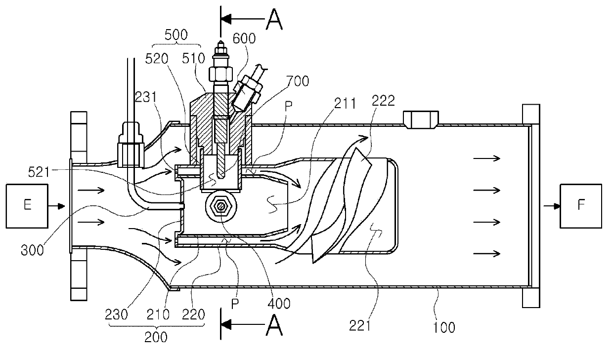
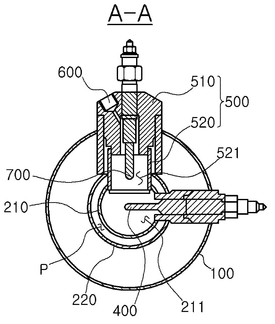
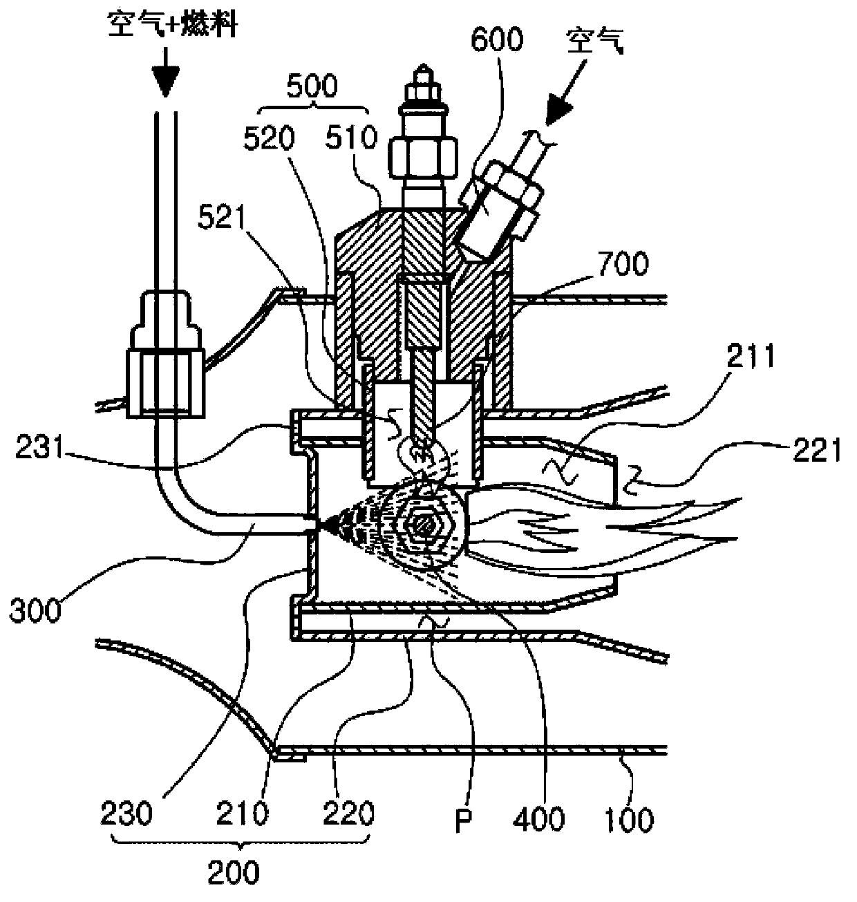
[0055] Such as figure 1 as shown, figure 1 is a cross-sectional view illustrating a cross-section of an exhaust gas reducing device according to an embodiment of the present invention; figure 2 yes figure 1 Sectional view of line A-A in middle; image 3 It is an enlarged view showing the first combustion part and the second combustion part of the exhaust gas reduction device according to the embodiment of the present invention; Figure 4 It is a diagram illustrating the operating state of the exhaust gas reduction device according to the embodiment of the present invention.

[0056] figure 2 In order to show the swirling body formed in the flame part, the partial section of the flame part is not shown; in figure 1 and Figure 4 In , the flow of exhaust gas is marked by arrows.

[0057] The tail gas reduction device of the embodiment of the present invention is as Figure 1 to Figure 4 As shown, it is composed of an exhaust pipe 100 , a first combustion unit 200 , a n...


PUM


Abstract

PURPOSE: An exhaust gas reducing apparatus is provided to stably maintain the temperature of exhaust gas as the flame in a second combustion chamber is rapidly ignited even in the case the flame in a first combustion chamber is extinguished. CONSTITUTION: An exhaust gas reducing apparatus comprises an exhaust pipe(100), first and second combustion units, an injection nozzle(300), first and second igniters, and an air feeder(600). The exhaust pipe delivers exhaust gas to an exhaust gas filter(F). The first combustion unit is installed inside the exhaust pipe, and placed between an engine and the exhaust gas filter. The first combustion chamber comprises a first combustion chamber(211). The injection nozzle is mounted into the first combustion unit, and injects a mixture mixed with air and fuels to the first combustion chamber. One end of the first igniter is placed inside the first combustion chamber, and ignites the mixture injected from the injection nozzle. The second combustion unit comprises a second combustion chamber(521) connected to the first combustion chamber. The air feeder supplies the air to the second combustion chamber. One end of the second igniter is placed inside the second combustion chamber.

Description

technical field [0001] The invention relates to the field of reducing tail gas emissions, in particular to a device for reducing tail gas. Background technique [0002] Generally speaking, trains, ships, and industrial vehicles usually use diesel engines, and cars are increasingly using diesel engines. [0003] With the increasing use of diesel engines, the emissions of suspended particulates such as soot, soluble organic fraction (Soluble Organic Fraction) and nitrogen oxides in the exhaust emitted by diesel engines are also increasing. These emissions are the cause of environmental pollution. The main reason, and therefore its control is getting stronger and stronger. [0004] In order to solve the above-mentioned environmental pollution problems, various schemes that can prevent the exhaust gas produced by diesel vehicles from being discharged into the atmosphere, capture and treat soot, and reduce exhaust emissions are all under study. [0005] Among the exhaust gas re...

Claims


Application Information

Patent Timeline
IPC IPC(8): F01N3/025
CPCY02A50/2351B01D46/42F01N3/025F01N2610/08F01N2610/1453
Inventor 刘永焕赵再得丁榕泫郑建愚
Owner CLEANEARTH
Why Eureka
Try Eureka