
Device and method for cleaning a sensor in an exhaust system

a sensor and exhaust system technology, applied in the field of exhaust system cleaning devices and methods, can solve the problems of sensor surface contamination, soot accumulation on the sensor surface,

Active Publication Date: 2021-08-17
VOLVO CAR CORP
View PDF17 Cites 1 Cited by
  • Summary
  • Abstract
  • Description
  • Claims
  • Application Information

AI Technical Summary

Benefits of technology

[0008]By this first embodiment of an arrangement for cleaning an exhaust gas sensor, soot that is deposited on an exhaust gas sensor can be removed in an easy and cost-effective way. When soot deposits on an exhaust gas sensor, the readings of the sensor will become less accurate, and depending on the amount of soot, may even be useless. If the readings of the sensor are inaccurate, the amount of fuel injected into the engine may be incorrect, which will cause the air / fuel ratio of the combustion engine to be either too rich or too lean. This will in turn decrease the reduction of exhaust emissions and will increase the fuel efficiency, and may even damage the catalytic converter. An example of an exhaust gas sensor is a lambda sensor.
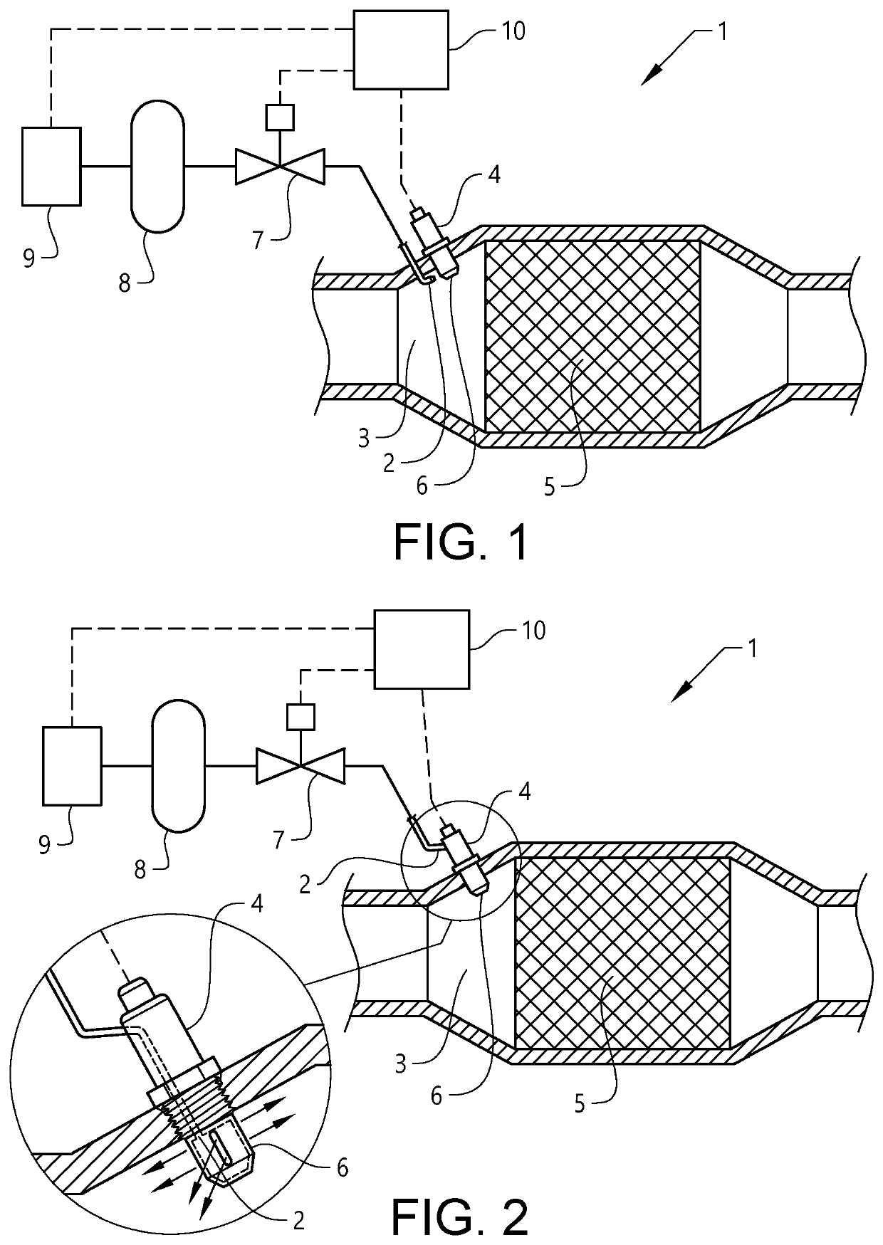
[0010]The blast of a fluid will cause the soot to come off mechanically, since the adhesion force of the soot is relatively weak. When air or an air / liquid mixture is used as a fluid, the added oxygen of the air will also help the soot to oxidize somewhat, which will help the cleaning of the exhaust gas sensor further. When the fluid is a mixture of a gas and a liquid, e.g. a mixture of air and 20% water, the air will contain a vapour when it is injected. The vapour may help to clean the exhaust gas sensor further. The fluid blast is directed on the protective cover of the lambda sensor, which is provided with several openings to allow exhaust gas to enter the lambda sensor such that the exhaust gas can reach the sensor surface of the ceramic sensor element. The fluid blast will in this case remove soot that has covered the openings of the protective cover. The fluid may also remove soot that has deposited on the sensor surface of the lambda sensor.
[0011]In a further embodiment, the fluid outlet is arranged inside the exhaust gas sensor. In this case the fluid blast will be ejected inside the protective cover, and the fluid will remove the soot deposited on the openings from the inside. The fluid will also help to remove any soot that has deposited on the sensor surface of the exhaust gas sensor.
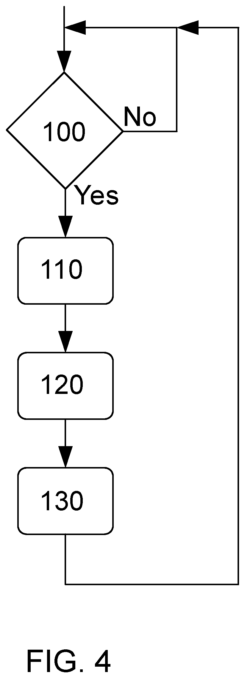
[0013]By this first embodiment of the method, the method will be able to remove soot from an exhaust gas sensor. The fluid pulse may comprise a single fluid blast or may comprise a series of short fluid blasts. In this way, the readings from the exhaust gas sensor will be correct. By removing soot that has deposited on the openings of the protective cover of the exhaust gas sensor, the exhaust gas will be able to enter into the exhaust gas sensor and reach the sensor surface of the exhaust gas sensor.

Problems solved by technology

One problem that may occur is that the surface of a sensor in the aftertreatment system of a vehicle, e.g. the surface of a lambda sensor, may be contaminated.
Soot may deposit on the sensor surface over time.
If too much soot deposits on the sensor surface, the measurements of the sensor may be incorrect.
Depending on e.g. the driving conditions of the vehicle, this problem may be more or less noticeable.
If the vehicle is driven for short intervals in a moderate speed, more soot may deposit on the sensor surface.
This solution functions when the exhaust gas temperature is high, but is not adapted for internal combustion engines.
When soot deposits on an exhaust gas sensor, the readings of the sensor will become less accurate, and depending on the amount of soot, may even be useless.
If the readings of the sensor are inaccurate, the amount of fuel injected into the engine may be incorrect, which will cause the air / fuel ratio of the combustion engine to be either too rich or too lean.
This will in turn decrease the reduction of exhaust emissions and will increase the fuel efficiency, and may even damage the catalytic converter.
The blast of a fluid will cause the soot to come off mechanically, since the adhesion force of the soot is relatively weak.

Method used


Image

  • Device and method for cleaning a sensor in an exhaust system
  • Device and method for cleaning a sensor in an exhaust system
  • Device and method for cleaning a sensor in an exhaust system

Examples


Embodiment Construction

[0020]The embodiments of the invention with further developments described in the following are to be regarded only as examples and are in no way to limit the scope of the protection provided by the patent claims. The used fluid may be a gas, a liquid, or a mixture of a gas and a liquid. In the described examples, air will be used as an example of a fluid.

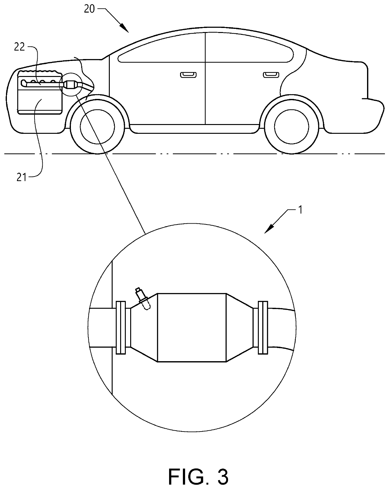
[0021]FIG. 1 shows a first embodiment of an arrangement for cleaning an exhaust gas sensor of a vehicle comprising a combustion engine, FIG. 2 shows a second embodiment of an arrangement for cleaning an exhaust gas sensor of a vehicle comprising a combustion engine, and FIG. 3 shows vehicle comprising an arrangement for cleaning an exhaust gas sensor.

[0022]The vehicle 20 comprises a combustion engine 21, which may be a diesel engine, a gasoline engine or an engine using liquefied natural gas or compressed natural gas. The vehicle may be powered solely by the combustion engine, or may be a hybrid vehicle. The combustion engine compr...


PUM

PropertyMeasurementUnit
pressureaaaaaaaaaa
air pressureaaaaaaaaaa

Abstract

An arrangement adapted for removing soot from an exhaust gas sensor in an exhaust gas system of a vehicle comprising a combustion engine, where the arrangement comprises a fluid outlet arranged in an exhaust gas conduit, and where the fluid outlet is adapted to impinge a blast of fluid on the exhaust gas sensor. The advantage of the invention is that an exhaust gas sensor can easily be cleaned in order to ensure a correct reading from the sensor.

Description

CROSS-REFERENCE TO RELATED APPLICATION[0001]The present patent application / patent claims the benefit of priority of co-pending European Patent Application No. 18165056.5, filed on Mar. 29, 2018, and entitled “DEVICE AND METHOD FOR CLEANING A SENSOR IN AN EXHAUST SYSTEM,” the contents of which are incorporated in full by reference herein.TECHNICAL FIELD[0002]The present invention relates to an arrangement, a vehicle and a method for cleaning a sensor in an exhaust system of a vehicle comprising a combustion engine.BACKGROUND ART[0003]Vehicles comprising an internal combustion engine are subjected to a plurality of different legislative requirements and regulations. Some of these requirements and regulations are directed to fuel consumption and exhaust emission. Different countries or markets may have different requirements, but most include a specific test cycle that is supposed to give an indication of the fuel consumption and exhaust emission of the vehicle. In another test, exhaus...

Claims


Application Information

Patent Timeline
Patent Type & Authority Patents(United States)
IPC IPC(8): F01N13/00F01N3/30G01N27/22
CPCF01N13/008F01N3/30F01N2560/02F01N2560/20G01N27/226F02B77/04F01N11/007Y02T10/12
Inventor ORBAY, RAIK
Owner VOLVO CAR CORP
Learn More