
Control device for internal combustion engine and method for controlling the same

A technology for control devices and internal combustion engines, which is applied in engine control, internal combustion piston engines, electrical control, etc., and can solve problems such as the inability to know fuel efficiency

Inactive Publication Date: 2013-10-30
MITSUBISHI ELECTRIC CORP
View PDF6 Cites 37 Cited by
  • Summary
  • Abstract
  • Description
  • Claims
  • Application Information

AI Technical Summary

Problems solved by technology

[0012] In addition, although the boost pressure can be controlled by using the opening of the wastegate valve, the boost pressure can also be controlled by using the opening of the throttle valve, so for the case of controlling the same boost pressure, there will be multiple exhaust gas The combination of the bypass valve opening and the throttle valve opening has the following problems: it is impossible to know which operating point has the best fuel efficiency

Method used


Image

  • Control device for internal combustion engine and method for controlling the same
  • Control device for internal combustion engine and method for controlling the same
  • Control device for internal combustion engine and method for controlling the same

Examples


Embodiment approach 1

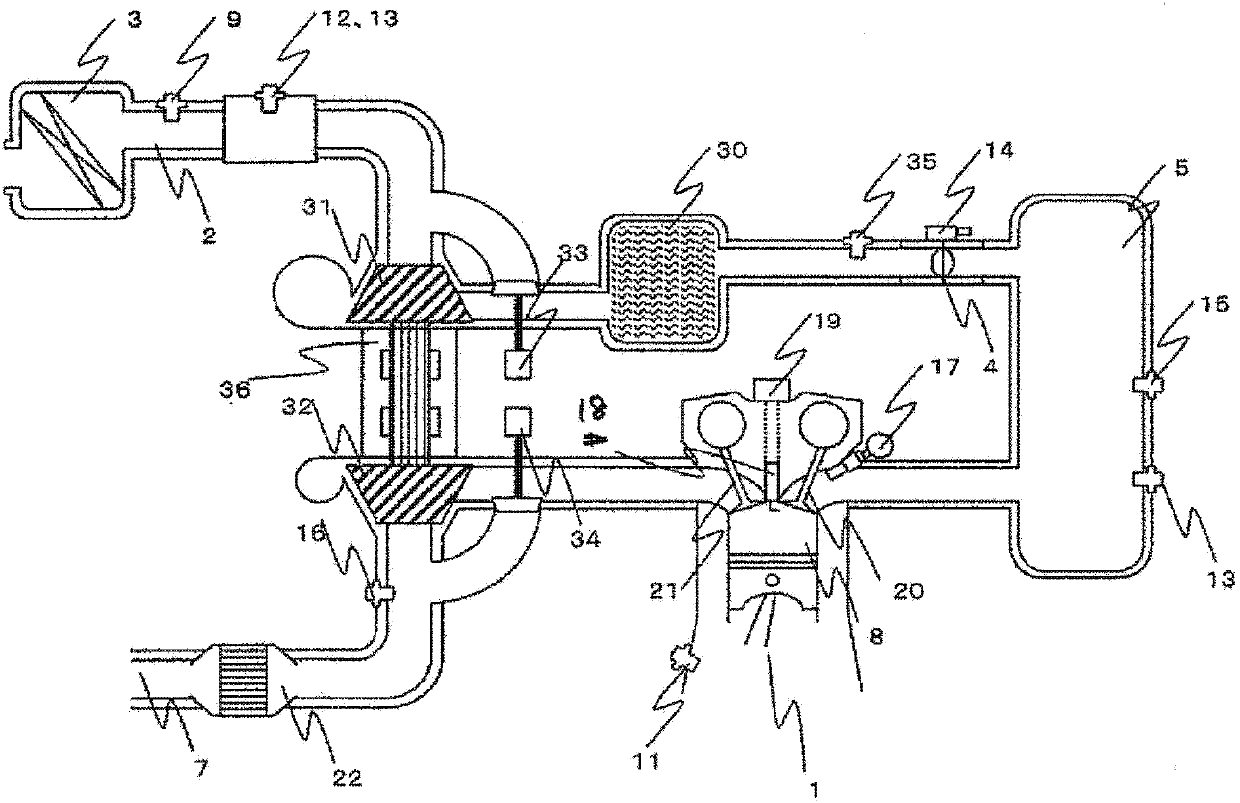
[0030] figure 1 It is a block diagram showing the intake / exhaust system of the internal combustion engine according to the present invention. figure 1 Among them, a crank angle sensor 11 for generating an electrical signal corresponding to the rotation angle is installed on the crank of the engine 1 . An intake port and an exhaust port of a combustion chamber of the engine 1 are respectively connected with an intake pipe 2 forming an intake path and an exhaust pipe 7 forming an exhaust path.

[0031] On the upstream side of the intake pipe 2 (opposite side to the engine 1 ), an air filter 3 for purifying the inhaled outside air is installed. On the downstream side (engine 1 side) of the air filter 3 of the intake pipe 2, the air flow sensor 12 that generates an electrical signal corresponding to the intake air flow rate, and the air flow sensor 12 that generates an electrical signal corresponding to the intake air temperature in the intake path are provided. The intake air t...


PUM


Abstract

Provided is a control device for an internal combustion engine, capable of controlling acceleration-response characteristics, performing an operation at an optimal fuel-efficiency point, and learning variation factors in an internal combustion engine provided with a supercharger including a wastegate valve. A target throttle-valve upstream pressure is calculated based on a target charging efficiency and a rotation speed. An exhaust-gas flow rate is calculated based on an air / fuel ratio and an intake-airflow rate. A target compressor driving force is calculated based on a target intake-airflow rate and a target throttle-valve upstream pressure. A wastegate-valve control value is calculated from the exhaust-gas flow rate and the target compressor driving force by using the relationship in which the relation expression expressing the characteristics of the exhaust-gas flow rate and the target compressor driving force depends only on the wastegate-valve control value.

Description

technical field [0001] The present invention relates to a control device for an internal combustion engine that controls an internal combustion engine provided with a supercharger including a turbine provided on an exhaust path and a compressor provided on an intake path. Background technique [0002] In the prior art, for the purpose of increasing the output of an internal combustion engine (hereinafter referred to as an engine), etc., there is known a turbocharger having a supercharger mounted on an intake path of the engine, which utilizes exhaust gas to Spin the turbine for motion. In this turbocharger, when it is in a state of high speed and high load, the boost pressure may increase above the required pressure and damage the engine. Therefore, there is usually an exhaust bypass passage upstream of the turbine. The wastegate valve on the exhaust bypass path diverts part of the exhaust gas flowing through the exhaust path to the bypass path to adjust the amount of exhau...

Claims


Application Information

Patent Timeline
Patent Type & Authority Applications(China)
IPC IPC(8): F02D23/00
CPCF02D23/00Y02T10/144F02B33/44F02B37/16F02B37/18F02B39/16F02D23/02F02D41/0007F02D41/18F02D2200/0406F02D2200/0414Y02T10/12
Inventor 绵贯卓生叶狩秀树
Owner MITSUBISHI ELECTRIC CORP
Learn More