Driving device of LED tube

A technology of LED lamp tubes and driving devices, which is applied in the direction of lighting devices, lamp circuit layout, light sources, etc., can solve the problems of high manufacturing cost, high electromagnetic noise, and defects, and achieve the effect of reducing design costs and reducing the ratio of defects

Active Publication Date: 2013-10-30
TPV ELECTRONICS (FUJIAN) CO LTD
View PDF3 Cites 4 Cited by
  • Summary
  • Abstract
  • Description
  • Claims
  • Application Information

AI Technical Summary

Problems solved by technology

[0004] The design and manufacture of the LED lamp drive device of the existing liquid crystal display products is relatively expensive and difficult
For example, the electromagnetic noise generated by components such as power transistors and boost rectifier diodes in the DC-DC boost converter 12 is relatively large, resulting in increased design difficulty and cost of the electromagnetic interference suppression circuit in the AC-DC converter 11
Moreover, the PWM control chip used to control the switching of the power transistor in the DC-DC boost converter 12 itself has a weak anti-static discharge (ElectroStatic Discharge, ESD) capability, which may easily cause the liquid crystal display products using this LED lamp tube driving device There is a certain rate of defective products in the factory and in the market

Method used


Image

  • Driving device of LED tube
  • Driving device of LED tube
  • Driving device of LED tube

Examples


Embodiment Construction

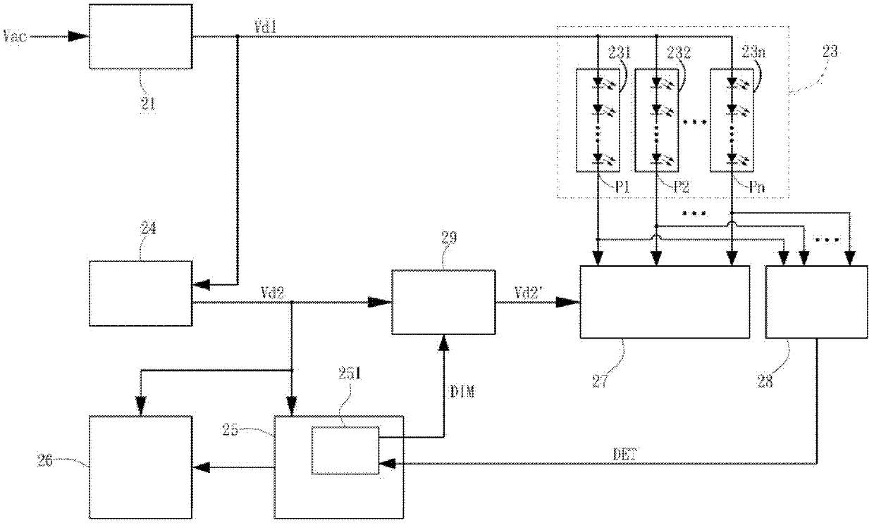
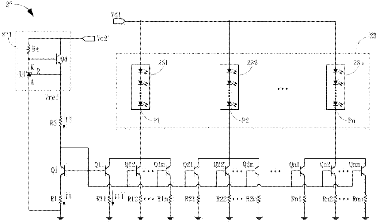
[0021] see figure 2As shown, the present invention includes AC-DC converter 21, LED lamp tube 23, constant current control circuit 27, protection circuit 28, control circuit 251 and dimming circuit 29; The power supply Vac is connected, and the output terminal outputs the first DC voltage Vd1; the LED lamp tube 23 includes n parallel connected LED lamp strings 231-23n, each LED lamp string has an input terminal and an output terminal P1-Pn, and each LED lamp string The input terminals 231-23n are coupled to the output terminal of the first DC voltage Vd1 of the AC-DC converter 21; the constant current control circuit 27 is coupled to the output terminals P1-Pn of each LED light string 231-23n to control each Whether the LED light strings 231-23n work normally or not, and control the current flowing through each LED light string 231-23n to be constant; the protection circuit 28 is coupled to the output of each LED light string 231-23n Terminals P1-Pn can output a protection s...


PUM


Abstract

The invention discloses a driving device of an LED tube. The method that a first direct-current voltage which can provide the working voltage of each LED light string of the LED tube is directly output by an AC-DC converter is applied to the driving device of the LED tube. The defects that after an existing AC-DC converter outputs a low direct-current voltage, a DC-DC boost converter is further needed so as to generate a high direct-current voltage which can be provided for the LED light string to enable the LED light string to work in the prior art are overcome. The driving device of the LED tube can reduce generated electromagnetic noise so as to reduce the design difficulty and the design cost of a needed electromagnetic noise interference suppression circuit. The driving device of the LED tube can further reduce the defect ratio of liquid crystal display products which are provided with the driving devices of the LED tubes in a factory and on the market so as to reduce the design cost of power sources of the liquid crystal display products. In addition, due to the fact that the existing DC-DC boost converter is not applied, a constant-current control circuit is adopted to ensure that each LED light string is in the constant-current state in the process of working. Besides, control over opening and closing of the constant-current circuit is used for controlling the average brightness provided by the LED tube. When the LED tube works and the detected voltage of the output end of the LED tube is larger than a protection point set valve, a dimming output port of the control circuit outputs a continuous low level signal to stop normal work of the constant-direct control circuit, the LED tube is finally switched off, and the purpose of protection is achieved.

Description

technical field [0001] The invention relates to a light source driving device, in particular to an LED lamp tube driving device which can be used in liquid crystal display products. Background technique [0002] Such as figure 1 Shown is a block diagram of a power supply system of an existing liquid crystal display product, the AC to DC (Alternating Current to Direct Current, AC-DC) converter 11 in the power supply system, the DC to DC (Direct Current to Direct Current, DC- A DC) step-up (boost) converter 12 and an LED lamp 13 constitute an LED lamp driving device, wherein the AC-DC converter 11 is, for example, an external power adapter. The AC power supply Vac for commercial use is input to the AC-DC converter 11, and a DC voltage Vdc1 of 12V-19V is generated after conversion. The DC voltage Vdc1 is input to the DC-DC boost converter 12 , and after being converted and boosted, a DC voltage Vdc2 that can provide the working voltage of the LED lamp 13 is generated. The DC...

Claims


Application Information

Patent Timeline
Patent Type & Authority Applications(China)
IPC IPC(8): H05B37/02
CPCY02B20/46Y02B20/40
Inventor 余祚尚庄锦清肖荣军
Owner TPV ELECTRONICS (FUJIAN) CO LTD
Why Eureka
Try Eureka