Device and method for creating and/or for transporting a layer transport flow of flat, flexible objects
A flexible object and sheet flow technology, applied in the directions of transportation and packaging, sending objects, object supply, etc., can solve the problems of flexibility impact, increase system cost and cost, etc., and achieve the effect of flexible use
Inactive Publication Date: 2013-11-06
BDT MEDIA AUTOMATION
6 Cites 3 Cited by
AI-Extracted Technical Summary
Problems solved by technology
[0004] But the shortcoming of above-mentioned equipment and method of forming and/or conveying lamellar flow is: used a vacuum chamber (or extractor, hereinafter referred to as vacuum chamber) that mandatory need vacuum generator; Vacuum generator and its required control Valves, vacuum pipes, etc. also significantly ...
Abstract
A device for the generation of a shingled stream of flat, flexible objects along a conveyor path, wherein successive objects develop an overlap with a length, includes a first and a second suction and conveyor device having a first and second unit, respectively, and each having at least one conveyor belt. The first and second units are each configured to generate a vacuum through a whirlwind to attract at least one of the objects and are each disposed in a casing having a suction aperture. The second suction and conveyor device is disposed downstream from the first suction and conveyor device in a direction of the conveyor path with a mutual offset corresponding to the length of the overlap and is disposed at an angle relative to the direction of the conveyor path. The first and second suction are separated by a spacing in a transversal direction.
Application Domain
Function indicatorsArticle feeders +1
Technology Topic
EngineeringMechanical engineering
Image
Examples
- Experimental program(1)
Example Embodiment
[0058] In the above icons, the same number indicates the same parts or parts with the same function; in order to ensure the clarity of the view, not all the numbers are marked in one view.
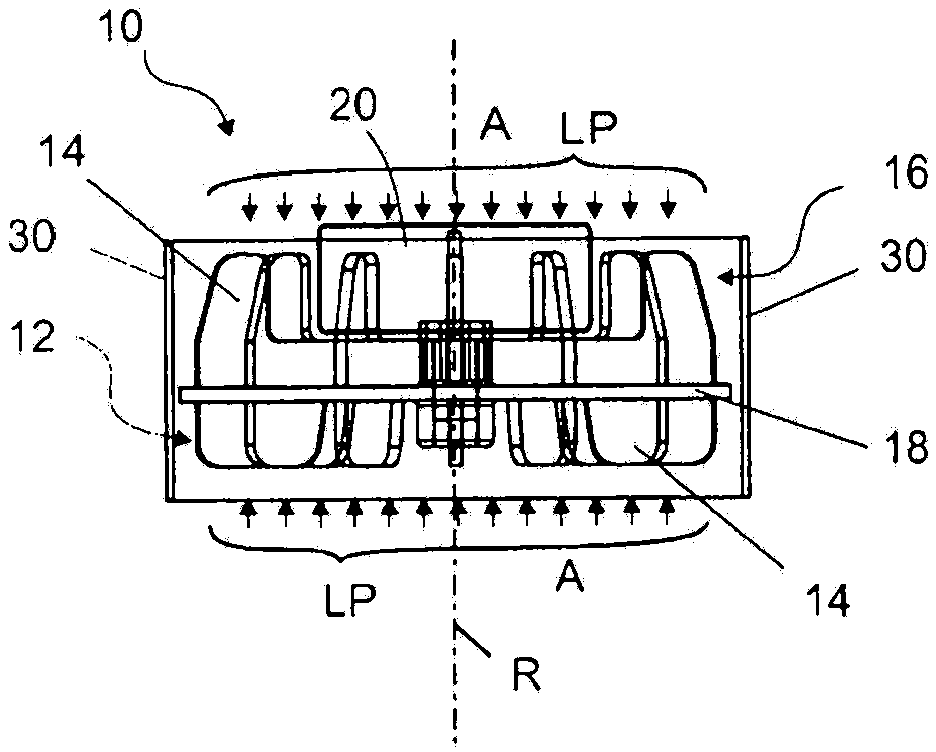
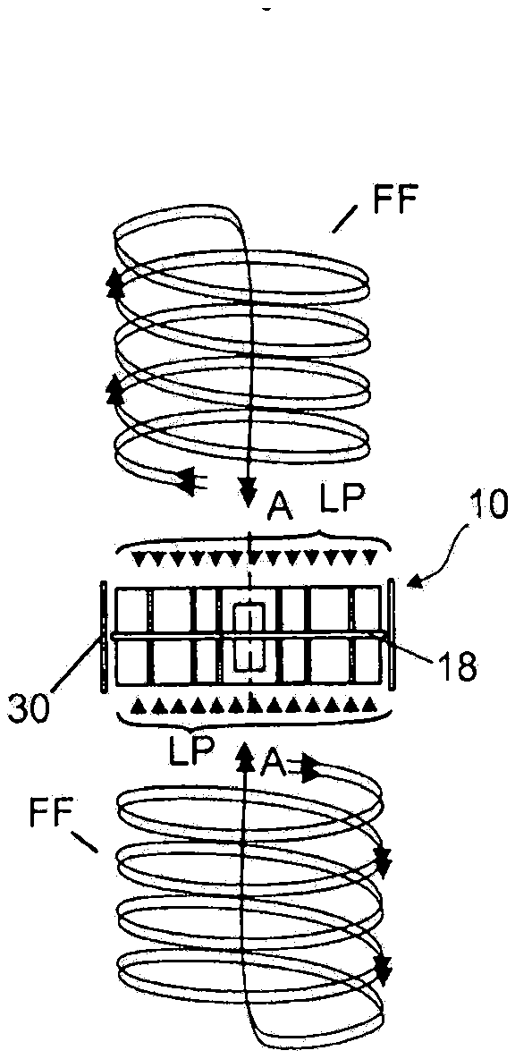
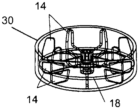
[0059] figure 1 The Vortex suction cup 10 shown is equipped with a lower impeller 12 driven by a motor 20. The lower-mounted impeller 12 has an isolation device 18 and a plurality of blades extending to the isolation assembly 18 in the radial direction. The blade 14 and the isolation assembly 18 rotate around the rotation axis R. Another similar configuration is an upper-mounted impeller 16 whose blades 14 extend to the isolation assembly 18 on the opposite side. The upper-mounted impeller 16 is preferentially selected among the above-mentioned two configurations of the impellers 12 and 16 to facilitate the cooling of the electric motor 20. The isolation assembly 18 can be installed symmetrically between the upper-mounted impeller 16 and the lower-mounted impeller 12; the upper-mounted configuration is preferred, and the upper-mounted impeller 16 has a lower height dimension than the upper-mounted impeller 12 and is beneficial to the motor 20 The cooling, and can generate enough vacuum for sucking the conveyed object 40. It should be pointed out that: Vortex sucker 10 only produces vortex airflow in the lower impeller 12 to suck the conveyed object (reference Figure 4 ).
[0060] The motor 20 may be either a DC motor or an AC motor. For example, the motor 20 is a brushless DC motor or a stepping motor, and is a motor with a rotation speed of 15,000 to 25,000 rotations per minute; the preferred range of the motor rotation speed is 20,000 rotations per minute. When a motor with this speed is used, when the impeller diameter is about 50mm and the blade height is about 8mm, the vacuum suction force that can be generated is 1.6N, and the conveyed object 40 is sucked at a distance of 4mm.
[0061] The blade 14 may be of different shapes, such as a shovel type. One of the shapes is a straight plate, arranged radially. This structure allows the impellers 12 and 16 to rotate in both directions.
[0062] Among the materials used for the above-mentioned upper-mounted impeller 16 and the lower-mounted impeller 12, light alloy materials can be selected, for example, plastic materials are used; the preferred impeller diameter is about 50 mm.
[0063] Another such as figure 1 In the structure shown, the upper edge, inner edge and radial edge of the blade 14 of the upper-mounted impeller 16 are not linear and have recesses; the motor can pass through these recessed parts when the blades rotate. As an alternative, the electric motor 20 may be arranged outside the upper impeller 16.
[0064] The Vortex suction cup 10 can be installed inside the housing; but when the partition 18 is used, the outer edges of the partition 18 and the blade 14 can be reached. The housing 30 can be either a shell type or an annular shape separated by blades 14 (see figure 1 ) In order to make the impeller a portable impeller. As an alternative, the impeller 12 and/or the impeller 16 can also be manufactured in a ring shape that is directly connected to the outer edge of the blade 14 or the isolating plate 18 to form the shell 30 (see image 3 ).
[0065] Every device capable of generating vortex airflow FF can be regarded as a Vortex suction cup. In particular, the airflow FF generated by the radially extending blades 14 can generate a vacuum zone LP in front of the impeller 12 (see figure 1 with figure 2 ). The air flow FF rotates around the rotation axis of the blade 14. The vacuum suction force A is generated by the vacuum zone LP, so that the Vortex sucker 10 can suck the conveyed object 40, and/or can move to the surface of the conveyed object when the Vortex sucker itself is not fixed. The Vortex sucker 40 is suitable for sucking the conveyed objects 40 with flat and uneven surfaces; if necessary, it can suck the objects to complete spatial movement.
[0066] Figure 5 to Figure 10 Shows a different view of the first suction and transport device M; the Vortex suction cup 10 they use is different from Figure 1 to Figure 4 The Vortex suckers shown are the same, they are all installed in the housing 30a, each with two transport belts 34. There is a suction port 33 on the housing 30a (see Image 6 ), under the suction port is the impeller 12 of the Vortex sucker 10. In order to prevent the transported object 40 from damaging the impeller 12 and the impeller 12 from causing damage to the transported object 40, the suction port 33 shown in this example is provided with multiple protective ribs 32, or is protected by a protective fence.
[0067] The transport belt 34 is an endless belt that is sheathed on the housing 30a. Each housing 30a has two drive rollers 36 on which a conveyor belt 34 is installed and two steering rollers 35. The conveyor belt 34 between the two driving rollers 36 serves as a supporting surface for conveying the moving object 40. The maximum length of the object 40 that can be placed on the conveyor belt 34 is the distance between the axis TA of the drive roller 36 (see Figure 7 ). Via the turning roller 35, the conveyor belt 34 turns to the side of the housing 30a opposite to the suction port 33.
[0068] In principle, it is possible to install more than one conveyor belt 34 on the driving roller 36 and the steering roller 35; instead, there can be two or more conveyor belts 34. These conveyor belts are arranged parallel to the side of the casing with the suction opening, upward through the driving roller 36 at the casing 30a, downward through the turning roller 35, and are sheathed between the two rollers. The conveyor belt 34 can be driven by an external drive device, for example, a drive motor 37a driven by a drive roller 36, such as Figure 5 The structure shown. The advantage of this external drive method is: the parallel working suction and transport device can be driven by the clutch, for example, the clutch can drive the entire drive roller, such as Figure 24 Shown. It can also be driven by the belt motor 37 built into each suction and transport device M itself (see Figure 7 ). The belt motor 37 may be a stepper motor, a DC motor, or an asynchronous AC motor. In one configuration of the invention of this patent, a transmission 38 is also arranged between the belt motor 37 and the drive roller 36 (see Figure 7 ).
[0069] The suction and transportation device M may have its own controller 39; the controller monitors the working conditions of the belt motor and the like when the motor 20, the impeller 12 and the belt motor 37 are provided. Among them, the preferred configuration mode should be: both the motor 20 and the belt motor 37 should be able to be independent, independent of other suction and transportation devices, and achieve independent and stepless adjustment during the production process. A flat flat cable 39a can be used to control the controller 39.
[0070] Picture 9 Shown is Figure 7 A schematic diagram of the medium suction and transport device M using the vortex airflow to generate a vacuum to suck the transported object 40 on the transport belt 34 at a certain distance; see also Picture 10. After the conveyor belt 34 is driven, the conveyed objects 40 move on the conveyor belt 34.
[0071] Figure 11 to Figure 16 Shown are views of different configurations of the suction and transport device M; among these different configurations, the main difference is that the installation position of the conveyor belt 34 is different. Figure 5 to Figure 10. in Figure 5 to Figure 10 In the suction and transport device M shown, the transport belt 34 does not cover the suction port 33; Figure 11 to Figure 16 In the suction and transportation device M shown, the conveyor belt 34 passes above the suction opening 33. The conveyor belt 34 passing above the suction opening 33 has only a small effect on the suction force. Especially when the conveyor belt 34 is a flat belt, such as a flat belt with a thickness of only 0.8 mm and a width of about 15 mm; in comparison, the diameter of the suction opening 33 is about 50 mm. Although the suction port 33 is partially covered, the vortex air flow generated by the impeller 12 has sufficient suction force to well adsorb the conveyed object. The advantage of the conveyor belt 34 disposed above the suction port 33 is that the protective rib 32 or similar protective devices can be omitted; because the conveyor belt 34 itself can prevent the conveyed object 40 from contacting with the blade 14 of the impeller 12 and damage the conveyed object. Another advantage of the conveyor belt 34 being arranged above the suction opening 33 is that it allows the conveyed object 40 to bend itself, such as Figure 16 Shown. The conveyed object 40 is arc-shaped, and the projection transverse to the conveying direction TR is relatively short; thus, the conveyed object 40 can be conveyed and placed in parallel without extending the length of the conveyed object 40 on the conveying path. The decrease in width is affected by the relative position between the conveyor belt 34 and the suction opening 33. At the same time, the smaller width is also related to the bending strength of the conveyed object 40 and the suction force of the Vortex sucker 10. Thinner objects with low bending strength can be easily bent, while objects 40 with larger weight per unit area and/or higher bending strength require a higher suction force to present a desired arc shape. In the formation of the arc, the elasticity of the conveyor belt 34 has a very helpful effect: when it is subjected to suction near the suction port 33, it keeps matching with the arc of the conveyed object 40, such as Figure 16 Shown.
[0072] Figure 17 The bending of the conveyed object 40 can be seen again. Figure 17 It shows the condition that two suction and transport devices M and the transported object 40 are transported in this equipment. The view shows the conveying situation transverse to the conveying direction, that is, perpendicular to the paper surface. Below the suction and transport device M is the storage area where the transported objects are placed; these objects are not bent in the horizontal direction; therefore, the distance A1 shown in the figure is obviously smaller than the transported objects 40 when they are suspended on the suction and transport device. The spacing A2 when the shape is bent.
[0073] Figure 18 with Figure 19 Shown are other advantages of the suction and transport device M. Tests and tests have proved that the suction port 33, especially the projection surface of the impeller, does not need to be completely covered, so that suction can be generated within a distance of 40 mm in front of the suction port 33. When 30% of the entire area of the suction port 33 is covered by the conveying object 40, the suction force 4 mm in front of the suction port 33 still reaches 1.2N. Such as Figure 18 As shown, although there is an open area O and a partially covered area G at the suction port 33, the suction and transport device M can still reliably suck the conveyed object 40.
[0074] In addition, a plurality of transported objects 40 may be sequentially fed into the suction port 33 of one suction and transport device M along the transport direction TR. This makes it possible, for example, to transport paper with a unit area weight of 80 g/qm, such as DIN standard A4, by a suction and transport device M. When the bending strength of the transported object 40 and the arc caused by the suction and transport device M meet certain requirements, the transported object can be transported to the next suction and transport device M by means of suspended transport (see Picture 20 ). Used for the suction force at the maximum 50mm in front of the suction port 33, the conveyed object 40 can be picked up by the latter suction and transport device under the action of vacuum, and sent to the subsequent suction device through the conveyor belt 34 of the next suction and transport device 33 places. Moreover, there may be a certain gap d between the two conveyed objects 40 along the conveying direction TR, such as Picture 20 Shown. The suction and transport devices M, M'can not only take the transported objects 40, but also continue to transport them, even when the suction port 33 is only partially covered.
[0075] in Figure 18 with Figure 19 , You can see that the attached support member 50 is added; this attachment support has a very good enhancement effect in the conveying of the conveyed object 40 along the conveying direction; for example: Figure 18 It can be seen that the attached supporting member 50 is, for example, a steel cable, and the beneficial enhancement effect it brings to the conveyed object 40 is that the supporting area of the conveyor belt 34 is increased.
[0076] Figure 21 The device 60 shown is a device that makes the conveyed object 40 form and transports a sheet flow; the icon device 70 is a device that makes the conveyed object 40 form a sheet flow; the icon device 90 is a device that transports a sheet flow. It should be noted that the drawing device 70 does not need to be combined with the icon device 90; on the contrary, they can all be completely independent devices 70 and 90. The device 70 and the device 90 may be arranged to be spaced apart from each other in sequence along the transport direction TR at a distance D2-3.
[0077] The device 70 is used to form a sheet-like stream of a flat flexible object 40 (such as an object 40 cut according to the paper size). It instructs the transport device M1 to perform the first suction and the transport device M2 to perform the second suction. The suction and transport devices M1 and M2 can be as Figure 5 to Figure 10 ,or Figure 11 to Figure 16 Set up as described in the suction and transport device M. It is important that the settings of the suction and transport devices M1 and M2 must be the same.
[0078] The object 40 (located at the positions identified by S1, S2, S3, S4, S5, S6, S7, S8, S9 in the device 60) will move along the transport path TP in the transport direction TR. The device 70 for forming the sheet-like flow of the objects 40 transports the objects 40 (cross-cut and vertical-cut) cut by the cutting device SE in order without stacking (see position 49). The velocity of the object 40 at the input port is Ve. The first suction and transportation device M1 and the second suction and transportation device M2 are respectively installed on two sides of the transportation path TP. It should be particularly noted that the first suction and transport device M1 should be installed on the transport path TP, and in the transport direction TR before the second suction and transport device M2; the second suction and transport device M2 is installed on the transport path Below the TP. The length of the suction and transport devices M1 and M2 is LM, and the relative distance between them along the transport path TP is L. In the demonstration example, L is less than the length LM of a suction and transport device (M1 or M2), but it can also be greater than this length LM, for example, it can be greater than 25% of the LM length. For more details, please see Figure 22e. When choosing the length L, it should be considered that the suction cyclones of the suction and transport devices M1 and M2 should not cross each other, and it is better to leave a distance of SW (5 to 10 mm) between them, and they should rotate side by side (see Figure 22e ).
[0079] Such as Figure 21 with 22e As shown, the distance between the two suction and transport devices M1 and M2 in the direction transverse to the transport direction TP is AM. Although they are on both sides of the object 40, they are not completely overlapped. The misalignment AM can be from 3 to 25 mm. The most ideal is 10 to 15 mm.
[0080] Next note that from Figure 21 with Figure 22e It can also be seen that there is an included angle α between the second suction and transport device M2 and the transport direction TR or the transport path TP, and the included angle α ranges from 0 to 20 degrees, preferably about 10 degrees.
[0081] The movement of the object 40 between the two suction and transport devices M1 and M2 is as Figure 22a to 22d Shown. Here, the object 40 is also conveyed through the device 70, and thus forms a sheet-like flow of the object 40 (see Figure 22a ). The distance D1 between the objects 40 stacked in a scaly shape is between 2 and 30 mm, for example, 20 mm.
[0082] Because there is a vertical distance AM between the first suction and transport device M1 and the second suction and transport device M2 transverse to the transport path TP, when the object 40 passes through the suction opening 33 of the first suction and transport device M1 a distance Later, its front edge will droop (see Figure 22a ). The drooping front edge will ride on the transport belt 34 of the second suction and transport device M2. The running speeds of the conveyor belts of the suction and transport devices M1 and M2 are approximately the same.
[0083] When the rear edge of the object 40 reaches the middle position S9 of the suction port 33 of the first suction and transport device M1 (see Figure 22b ), depending on the object 40 to be transported, the speed of the conveyor belt 34 of the second suction and transport device M2 can be reduced to 10% to 90% of the input port speed Ve. Because the conveyor belt 34 of the first suction and transport device M1 continues to run at a constant speed, the object 40 is sent to the position S8 and placed on the object 40 that was previously at the position 37, thus forming a stack, or increasing The previous stacking height. If the object 40 being processed is relatively hard, it may slip off because the part of the object 40 that is transported faster on the first suction and transport device M1 will be blocked by the part of the second suction and transport device M2 that is transported slowly. . If the object 40 is thin and not too hard, it may appear as Figure 22c Ring sleeve shown. Because there is a distance AM between the first suction and transport device M1 and the second suction and transport device M2, the formed loop will not cause damage to the object 40. When the rear edge of the object 40 reaches the middle position of the suction port 33 of the second suction and transport device M2 (see Figure 22d ), the speed of the conveyor belt of the second suction and transport device M2 will be increased back to the original speed (that is, the input port speed Ve), so that even if the object 40 forms a loop, it can be deployed. So far, the object 40 can be transferred by the second suction and transport device M2 to the next processing equipment, for example, to the sheet-like flow transfer equipment 90 of the object 40 described below. Figure 23 Shown are two stacked objects 40, and the overlapping length transferred on the second suction and transport device M2 is The sheet-like flow formed by the device 70 still has the input port velocity Ve when it intersects with the next device.
[0084] The device 70 is used to form a sheet-like flow of the object 40, the overlapping length of which is The overlap length is defined by two objects 40 stacked adjacently (see Figure 22d ).
[0085] In the described apparatus 70 for forming sheet flow, the overlap length The speed of the conveyor belt 34 of the suction and transport device M1, M2, especially the transmission speed difference of the two suction and transport devices when the object 40 is passed from the first suction and transport device M1 to the second suction and transport device M2, is continuous Adjustment (see Figure 22a -d).
[0086] By controlling the speed of the conveyor belt, especially the speed of the second suction and transport device M2, the overlap length can be changed at any time Therefore, in the process of forming sheet flow, It is an adjustable variable, and the distance between adjacent stacked objects is variable.
[0087] The length of the non-overlapping portion of two adjacent objects 40 can be less than the length LM of one suction and transport device in M1 to M5, or even less than the diameter of the suction opening 33 of one suction and transport device in M1 to M5.
[0088] The first and second suction and transport devices M1 and M2 are mainly controlled by the controller 45 according to the cutting signal of the cutting device SE. The time point at which the transmission speed of the second suction and transport device M2 changes can be calculated according to the relationship between the length of the object 40, the bending strength and the object distance, and the calculation result can be made into a table for reference. For particularly hard or particularly soft objects 40, the suction force of the first and/or second suction and transport devices M1, M2 can be additionally adjusted to prevent slippage or form a large loop. During the operation of the equipment, the controller 45 can individually control the speeds of the suction and transport devices M1 and M2 conveyor belt 34 and the speed of the impeller 12 of the Vortex sucker 10 one by one.
[0089] The device 90 responsible for conveying the sheet-like flow of the object 40 must send the sheet-like flow to the storage 100 on the one hand, and reduce the speed of the object 40 on the other hand, so as to prevent the object 40 from being damaged during storage in the storage 100.
[0090] The equipment 90 has at least three suction and transport devices M3, M4, and M5, which are sequentially installed on the path TP along the transport path TP. The distance between the suction and transport devices M3 and M4 is D3-4, and the distance between M4 and M5 is M4-5. Due to the consideration of the cyclone and suction principle, the suction and transportation devices M3, M4, and M5 are not placed in close proximity. With D3-4 and D4-5, the transmission distance becomes longer, or for a given transmission distance, the number of suction and transport devices M3, M4, M5 required can be reduced.
[0091] The speed of the suction and transport device M3, M4, M5 conveyor belt 34 and the rotation speed of the impeller 12 of the Vortex sucker 10 can also be individually controlled by the controller 45 one by one.
[0092] When the sheet flow generating device 70 of the object 40 transfers the object 40 to the sheet flow transport device 90, the first suction and transport device M3 of the device 90 is in the transport direction TR with the transport belt 34 and the device 70 (which produces 40 pieces of objects). The running speed of the conveyor belt 34 of the second suction and transport device M2 is the same. The suction and transport device M3 sends the object 40 through the positions S7 and S6 to the position S5 in the direction of the subsequent suction and transport device M4. The conveyor belt 34 of the suction and transport device M4 first runs at a speed lower than the speed of the conveyor belt 34 of the suction and transport device M3, and the object 40 will pass from the position S5 through S4 to the position S3 of the subsequent suction and transport device M5. The conveyor belt 34 of the suction and transport device M5 first runs at a lower speed than the conveyor belt 34 of the suction and transport device M4. If another suction and transport device is also installed, the conveying speed of the conveyor belt 34 will become smaller and smaller, so that at the last suction and transport device, it will drop to the set outlet speed. The speed of the input port can reach 6 meters per second, and for some objects with suitable bending strength, it can even reach 8 meters per second. The ideal speed of the outlet is 1 m/s or less. If the object has reached the last suction and transport device M5, the front edge of the object 40 will collide with the stacking edge 102, and the object 40 on the conveyor belt 34 of the suction and transport device M5 will continue to be transported along the transport direction TR. As the subsequent objects 40 are stacked, the objects 40 walking ahead will be blocked by the conveyor belt 34 of the suction and transport device M5 (please compare the two objects 40 at positions S2 and S1), and then fall to the storage device 100.
[0093] By default control and change of the speed of the conveyor belt 34 of different suction and transport devices M3, M4, M5, the stacking length of the sheet flow of the object 40 can be continuously adjusted with reference to the length of the device 90. If necessary, the sheet flow can be accumulated for a short time to form a longer stack length. The length can be adjusted if necessary in the subsequent transportation. For example, when too many task parts 40 have been stored on the storage device 100 and the storage device must be emptied or replaced, the foregoing short-term accumulation is advantageous. When the storage device 100 has been emptied or replaced, the flow of the accumulated objects 40 can be readjusted by controlling the speed of the subsequent suction and transport device, so that the objects 40 can be stored on the replaced or emptied storage device as usual.
[0094] The tail speed can be adjusted by the last stage of the suction and transport device (the suction and transport devices M4 and M5 are seen in the picture). For example, when the input port speed is 5 m/s, the final speed can be adjusted to 1 m/s. The most ideal tail speed is the maximum speed defined according to the following conditions: when the object 40 reaches the stacking edge 102, the object will not be damaged, nor will it move back due to its elasticity and/or appear chaos on the storage device 100. For most objects 40, the speed is about 1 m/s, and its size depends on the object 40, and should be lower than this value if necessary. The conveyor belt 34 of the last stage suction and transport device M5 runs at this ideal speed, and the objects 40 are also stored on the storage device at this speed. For example, the speed of the suction and transport device M4 at the previous stage is 2.5 m/s, and the speed of the suction and transport device M5 at the subsequent stage is reduced to 1 m/s. If the object 40 is thin and has low bending strength, of course, the suction and transportation device can be used to further reduce the tail speed, for example, it can be reduced to 0.8 m/s. In addition. It is also possible to use more suction and transport devices to increase the speed of the input port while the tail speed remains unchanged at 1 m/s. The greater the speed difference between the inlet and outlet, the more suction and transport devices are required in principle.
[0095] Through the controller 45, the speed of the suction and transport devices of each stage of M1 to M5 can be adjusted as desired, which is the more flexible device 60.
[0096] In addition, the controller 45 can also control the speed of the impeller 12 of the Vortex suction cup 10 of each stage of the suction and transport device of M1 to M5, thereby changing its suction. For most objects 40, in principle, the average suction force is about 0.8 Newtons, and a spacing of 4 mm is sufficient. For objects 40 with a thickness of 200 g/m2, the suction power of each suction and transport device from M1 to M5 must be 1.2 Newtons.
[0097] In addition, it is also meaningful to individually lower the suction power of each suction and transport device in M1 to M5. For example, for a thin object 40 with low bending strength, the strong curl formed by the suction ports 33 of the suction and transport devices M1 to M5 on the object 40 is very disadvantageous during the transmission process. Therefore, the rotation speed of the motor 20 of the Vortex suction cup 10 can be reduced to make The suction force for the object 40 is appropriate. Normally, the suction power of each suction and transport device of M1 to M5 is almost the same. If necessary, the suction force of each of the suction and transport devices of M1 to M5 can be adjusted, for example, it can be adapted to different friction forces through such adjustment. This is especially applicable to the first suction and transport device M1. It may be more advantageous to have a smaller suction force. When the device 70 forming a sheet flow transfers the object 40 to the device 90 and accelerates it, the object 40 is accelerated for a short time It has the same maximum speed as the input port speed Ve.
[0098] The device 60 has suction and transport devices M1 to M5, and it can process paper of a common size in the paper processing industry. For example, the device 60 described here is installed with five suction and transport devices from M1 to M5 in sequence. The size of the paper that can be transported ranges from 80 mm in length and 110 mm in width to 530 mm in length and 210 mm in width, and the paper weight is from 40 g/m2 To 250 g/m². The distance between the suction and transport devices M1 to M5 can be kept constant. The minimum length of paper that the device can transport depends only on the size of the suction and transport devices M1 to M5. If the length LM of the suction and transport devices M1 to M5 is 110 mm, the minimum length of the object 40 that can be transported from one suction and transport device to the next is 80 mm. Of course, if a smaller suction and transport device is used, smaller objects 40, such as credit cards and postage-sized objects 40 can be transported.
[0099] To form a sheet-like flow of a super large object 40, such as 710 mm X 530 mm and a paper weight of 500 g/m2, multiple devices 60 must be used in parallel to reduce the tail speed of such a heavy and large object to a predetermined value. Figure 24 Shown in is such a set of equipment 60’. A single set of equipment 60 can be installed as a unit on the support rail AS in parallel with an interval AX. The spacing AX can be adjusted manually or with a motor. Depending on the size of the object 40, two sets of equipment 60 may be sufficient. Figure 24 Shown in is a situation where multiple sets of equipment 60 are installed in parallel. The equipment 60 can be installed equidistantly according to the width of the object 40. Pay special attention to the margin RA when determining the position of the device 60 according to the width of the object. The smaller the margin RA from the suction range to the edge of the object, the smoother the transmission of the object 40, especially when the transmission speed is 4 m/s. Note that the margin RA is less than 25 mm. This is particularly applicable in the stacking area. The front edge of the object 40 at position S8 is likely to encounter the edge of the subsequent object 40 that is raised at position S7, and the object 40 stacked at position S7 will be wiped and stacked without collision. Of the tail.
[0100] According to the device 60', the belt drive mechanisms of the suction and transport devices M1 to M5 sequentially installed in the device 60 can be driven by a single belt motor 37 of its transmission belt 34, or more commonly by means of a long shaft VT And each discrete drive motor to drive.
[0101] The device 60' can also simultaneously send objects 40 to the corresponding storage device 100 on multiple sets of devices 60 in parallel. At this time, it is allowed to reduce the width of the object 40, and parallel transmission and parallel storage (see Figure 17 ).
[0102] The holding force of a suction and transport device M1 to M5 of approximately 1.2 Newtons in principle allows the conclusion that, in order to transport and delay an object 40 having a DIN A3 size and a weight per unit area of 200 g/m2, the object is crosswise To guide toward the equipment 90 in the direction of transport TR, the holding force of a set of equipment 60 is sufficient, because the weight of the general object 40 is about 0.25 Newton. It should be noted that the object 40 travels at a speed of 5 m/s to 8 m/s during the transmission process, and the air will generate a lot of resistance. In particular, the object 40 does not travel by an angle, so it will shake at such a speed. In fact, at least another set of equipment 60 must be used for such object shape and speed. When determining the positions of the two sets of equipment 60 according to the width of the object 40, more attention should be paid to whether the edges of the object 40 can be covered, rather than whether the two sets of equipment 60 are equidistant on the object 40 to be conveyed.
[0103] The acceleration curve and acceleration time required in the operation and other control data for the object 40 will be determined by the given parameters (such as the weight and size of the object 40) and input to the central control device for programming. According to different selected objects, each function of each suction and transport device M1 to M5 involved in forming and transporting the sheet flow of the object 40 in the equipment 60 can be controlled by the controller 45.
[0104] With the aid of the device 70 for forming sheet flow and the device 90 for transporting sheet flow, flat flexible objects 40 of various sizes and materials can be transported. Plates, textiles, synthetic materials or paper can be transported. . According to the different objects 40 to be transported, the size and number of the required suction and transport devices M1 to M5 can be determined, or the number of sets of equipment 60, 70 and 90 required to form the equipment 60' can be determined.
[0105] In order to make the movement of the object 40 more flexible, you can Figure 25a with 25b As shown, the suction and transport devices M1 to M5 are successively placed in pairs on the plane of the object 40, forming an angle between β and γ, and the angle ranges from 0° to 60°. Figure 25a The placement in the middle can raise the object 40 upward from the horizontal by the β angle, and the placement in the 25b will push the object 40 downward from the horizontal by the γ angle.
[0106] In addition, suction and transport devices M1 to M5 can also be used on the plane of the object 40 as Figure 26 Placed as shown, the angles between adjacent devices are δ and ε, and the angle range is between 0° and 30°. In order to enable the object 40 to change direction on its plane, the conveyor belts 34 of the suction and transport devices M3 to M5 used can preferably be independently controlled, so that the running speed of two adjacent conveyor belts can be different. Figure 27 What is shown is just such a form of structure composed of the suction and transport device M''. The suction and transport device M’’ has two belt drive motors 37 and 37b, each of which drives a transmission belt 34, and the speed of each motor can be individually controlled.
[0107] List of drawing identifiers
[0108] 10 Vortex suction cup
[0109] 12 impeller
[0110] 14 blade
[0111] 16 impeller
[0112] 18 partition
[0113] 20 Motor, electric motor
[0114] 30 housing
[0115] 30a housing
[0116] 31 Fixed clamp ring
[0117] 32 Webs, ribs
[0118] 33 Suction port
[0119] 34 Conveyor belt
[0120] 35 Steering roller
[0121] 36 Transport roller
[0122] 37 Belt motor, belt motor
[0123] 37a belt drive
[0124] 37b belt drive
[0125] 38 Drive
[0126] 39 Single controller
[0127] 39a flat cable
[0128] 40 objects
[0129] 45 control unit
[0130] 50 support
[0131] 60 devices
[0132] 60’ equipment
[0133] 70 devices
[0134] 90 devices
[0135] 100 storage devices
[0136] 102 Stacking edge
[0137] M, M’, M’’ suction and transport device
[0138] M1 suction and transport device
[0139] M2 suction and transport device
[0140] M3 suction and transport device
[0141] M4 suction and transport device
[0142] M5 suction and transport device
[0143] R shaft
[0144] LP vacuum zone, negative pressure zone
[0145] FF airflow
[0146] TA bearing axis
[0147] TR transport direction
[0148] TP transportation route
[0149] L length
[0150] AM pitch
[0151] LM length
[0152] Overlap length, stack length, overlap length
[0153] SE cutting equipment
[0154] Ve entrance velocity
[0155] SW spacing
[0156] D1 spacing
[0157] D3--4 spacing
[0158] D4-5 pitch
[0159] AX spacing
[0160] RA margin
[0161] AS support rail
[0162] VT shaft
[0163] a spacing
[0164] d spacing
[0165] α angle
[0166] β angle
[0167] γ angle
[0168] δ angle
[0169] ε angle
PUM
Property | Measurement | Unit |
Spacing | 3.0 ~ 25.0 | mm |
Description & Claims & Application Information
We can also present the details of the Description, Claims and Application information to help users get a comprehensive understanding of the technical details of the patent, such as background art, summary of invention, brief description of drawings, description of embodiments, and other original content. On the other hand, users can also determine the specific scope of protection of the technology through the list of claims; as well as understand the changes in the life cycle of the technology with the presentation of the patent timeline. Login to view more.
Similar technology patents
Integrated construction project management system with handheld computer and checklist
Owner:BIRKNER CHARLES CHRISTIAN +2
Disposable medical-examination light
Owner:UTAH MEDICAL PRODS
Patient positioning support structure
Owner:WARSAW ORTHOPEDIC INC
Device for implementing a cutting balloon intervention with IVUS monitoring
Owner:SIEMENS HEALTHCARE GMBH
Classification and recommendation of technical efficacy words
- easy to use
Electrically programmable device with embedded eeprom and method for making thereof
Owner:SEMICON MFG INT (SHANGHAI) CORP