Buckling restrained steel plate shear wall with out-plane deformation space

A steel plate shear wall, buckling restraint technology, applied in the direction of walls, building components, earthquake resistance, etc., can solve the problems of easy cracking in the process of production, transportation and construction, weakening of the restraint effect of embedded steel plates, and the burden of concrete cover plates, etc., to achieve optimal Market application prospects, convenient manufacturing and construction, and good energy consumption

Inactive Publication Date: 2013-11-06
谭平
View PDF6 Cites 17 Cited by
  • Summary
  • Abstract
  • Description
  • Claims
  • Application Information

AI Technical Summary

Problems solved by technology

In the early design of steel plate shear wall, elastic buckling load was used as the limit state of bearing capacity, which resulted in very thick steel plates or very dense stiffeners, resulting in waste of materials and increased costs
However, for the thin steel plate, its lateral force mainly comes from the tension band formed after the steel plate buckles. The existence of the tension band makes the hysteretic curve of the thin steel plate wall have a serious pinching phenomenon. the sound of
[0003] From the perspective of the implementation effect of the traditional buckling-resistant steel plate shear wall, due to the large normal wall area, a prefabricate

Method used


Image

  • Buckling restrained steel plate shear wall with out-plane deformation space
  • Buckling restrained steel plate shear wall with out-plane deformation space
  • Buckling restrained steel plate shear wall with out-plane deformation space

Examples


Embodiment Construction

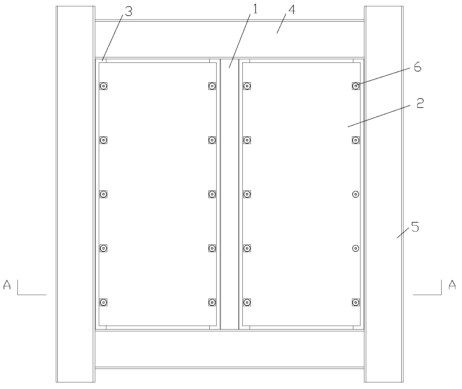
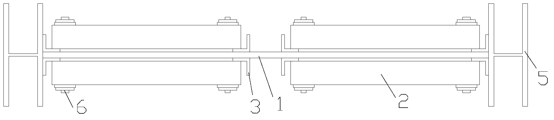
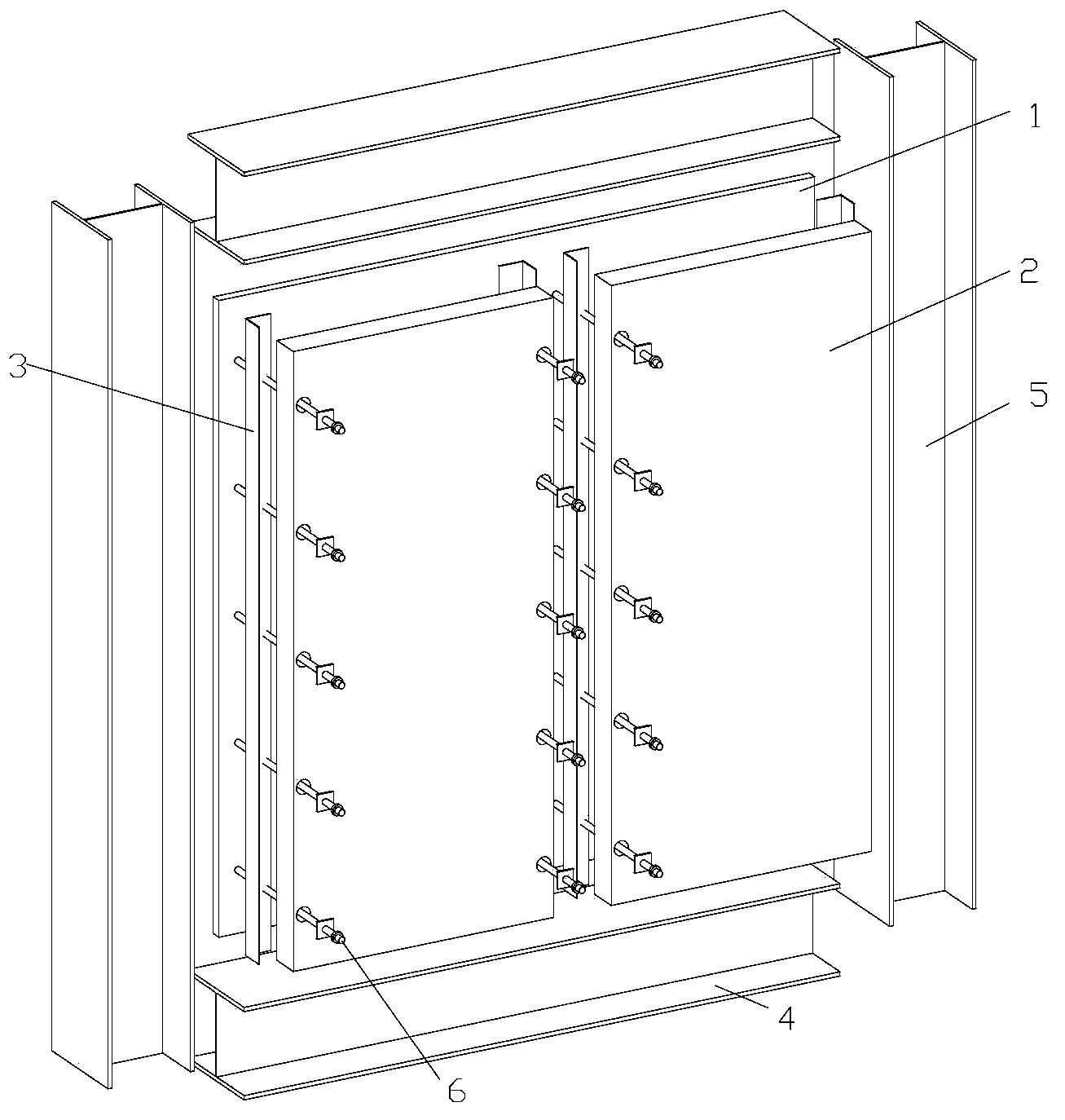
[0022] Figure 1 to Figure 3 Shown is Embodiment 1 of the buckling-constrained steel plate shear wall with out-of-plane deformation space of the present invention.

[0023] The shear wall includes an embedded steel plate 1 , a concrete cover 2 , edge members, and eight longitudinal stiffeners 3 . The embedded steel plate 1 adopts low yield point high ductility steel or high strength high ductility steel. The edge components include edge beams 4 and edge columns 5 , and the embedded steel plate 1 is located between the upper and lower edge beams 4 and is fixedly connected with the edge beams 4 . The longitudinal stiffeners 3 are symmetrically fixed on both sides of the embedded steel plate 1, that is, four longitudinal stiffeners 3 are arranged on each side of the embedded steel plate 1; is one longitudinal stiffener group, then the shear wall has four longitudinal stiffener groups in total. Each concrete cover 2 is fixed on the embedded steel plate 1 between the two longitu...


PUM


Abstract

The invention discloses a buckling restrained steel plate shear wall with out-plane deformation space and belongs to the technical field of structural engineering. The shear wall comprises an embedded steel plate, concrete cover plates, edge members and at least eight longitudinal stiffening ribs, wherein the edge members comprise edge beams and edge columns; the embedded steel plate is fixedly connected with the edge beams; the longitudinal stiffening ribs are symmetrically fixed on two sides of the embedded steel plate; every two adjacent longitudinal stiffening ribs on the same side form a longitudinal stiffening rib group; the distance between every two adjacent longitudinal stiffening rib groups ranges from 200 to 300 mm; all the concrete cover plates are fixed on the embedded steel plate between the two longitudinal stiffening ribs of each longitudinal stiffening rib group through connecting pieces; clearances are reserved between the concrete cover plates and the edge members, the reinforcing parts of the longitudinal stiffening ribs and the embedded steel plates. The shear wall has higher lateral stiffness and later bearing capacity and can effectively dissipate earthquake energy under the action of a rare earthquake.

Description

technical field [0001] The invention relates to the technical field of structural engineering, in particular to an energy-dissipating shear wall with relatively large lateral rigidity and relatively high late-stage bearing capacity. Background technique [0002] Steel plate shear wall is a new type of lateral force resistance structure developed in the 1970s. It has good ductility and ductility, large lateral stiffness, strong energy dissipation capacity, and outstanding seismic performance. Developed countries such as the United States and Japan have taken the lead in applying it to practical projects. In recent years, some high-intensity areas in my country have gradually begun to apply it, such as: Tianjin Tower in Tianjin, Shanghai Jinjiang Hotel, etc. In the early design of steel plate shear walls, the elastic buckling load was used as the limit state of the bearing capacity, which resulted in very thick steel plates or very dense stiffeners, resulting in waste of mater...

Claims


Application Information

Patent Timeline
IPC IPC(8): E04B2/56E04B1/98
Inventor 谭平李洋李高仰李文彦龙耀球
Owner 谭平
Why Eureka
Try Eureka