Image direct output device

An output device, direct technology, applied in projection device, installation, optics, etc., can solve the problems of light source penetration attenuation, weight increase, complex structure of components, etc., to achieve the effect of continuous beam resolution

Inactive Publication Date: 2013-11-06
BOHHEN OPTRONICS
View PDF6 Cites 2 Cited by
  • Summary
  • Abstract
  • Description
  • Claims
  • Application Information

AI Technical Summary

Problems solved by technology

[0005] Existing DLP or LCoS projection and display devices mainly perform color separation by rotating the color wheel, and then present colorful static and dynamic projection effects. However, limited by engineering technology and manufacturing costs, the existing color wheel is like Figure 9 The display is mainly through coating the required colors (such as R, G, B, etc.) on several glass substrates, and then cutting, collaging, and calibrating the balance according to the required size and shape. Therefore, the component structure of the existing color wheel is complicated, the weight is increased, and balance calibration is required to avoid the noise of the collage color wheel rotating at high speed, and because several substrates need to be pasted combined, so the penetration of the light source will be attenuated again;
[0006] Although there are a few high-end DLPs in the industry TM Compared with LCoS projection and display equipment, a single-chip color wheel is used. However, this kind of single-chip color wheel uses high unit price semiconductor lithography technology and equipment for protective layer photoresist coating, pattern mask, lithography exposure, Photoresist development, coating, etc. complete the first layer of color one by one. Such steps must be repeated continuously after required colors such as R, G, and B to complete a single-chip color wheel, so its manufacturing cost is almost higher than that of color filters for display panels. (Color Filter) price, relative to the cost of manufacturing and use, there is room for improvement

Method used


Image

  • Image direct output device
  • Image direct output device
  • Image direct output device

Examples


Embodiment Construction

[0023] The technical means adopted by the present invention to achieve the intended invention purpose are further described below in conjunction with the drawings and preferred embodiments of the present invention.

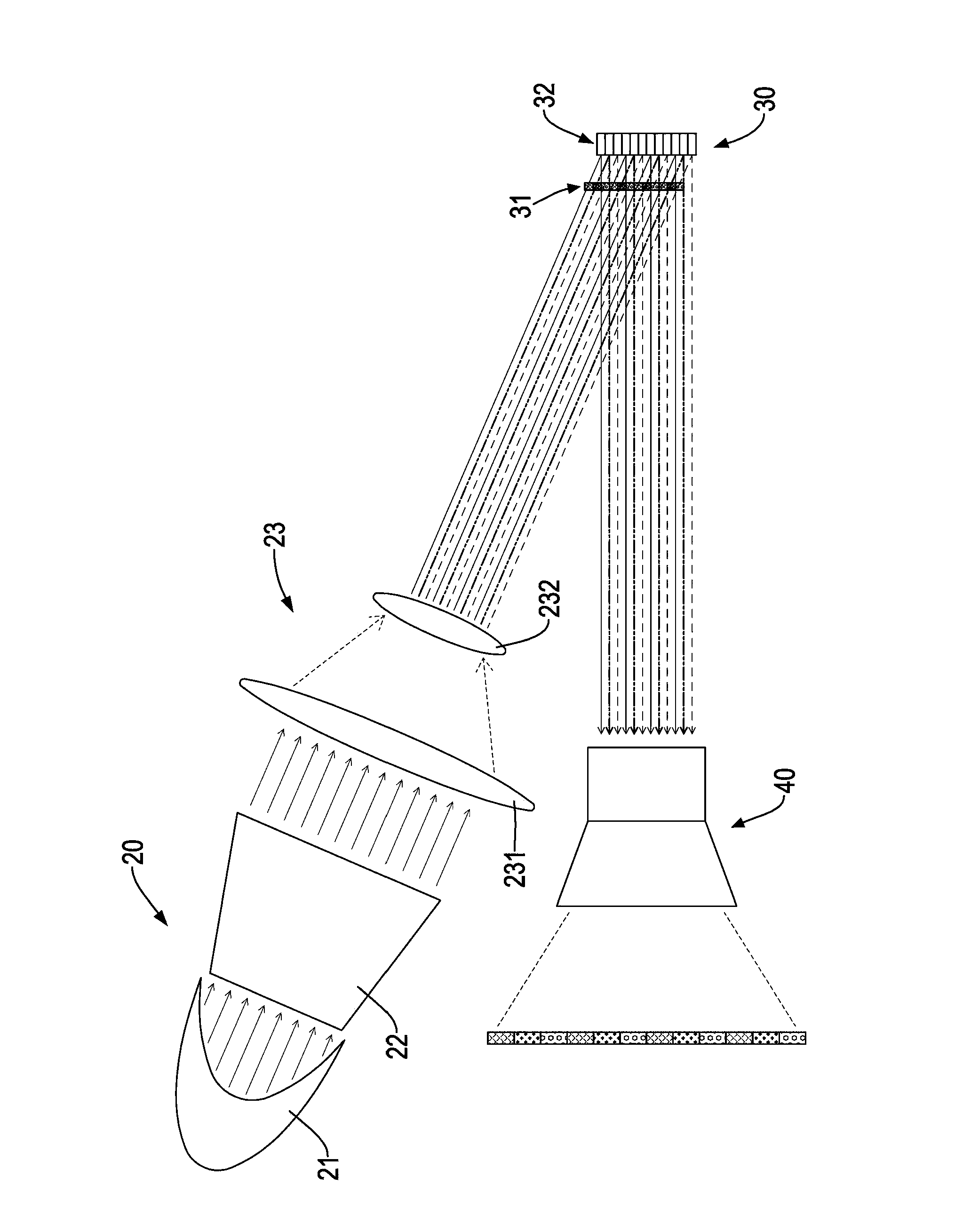
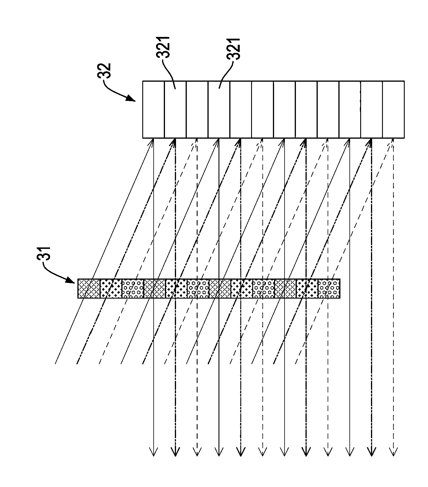
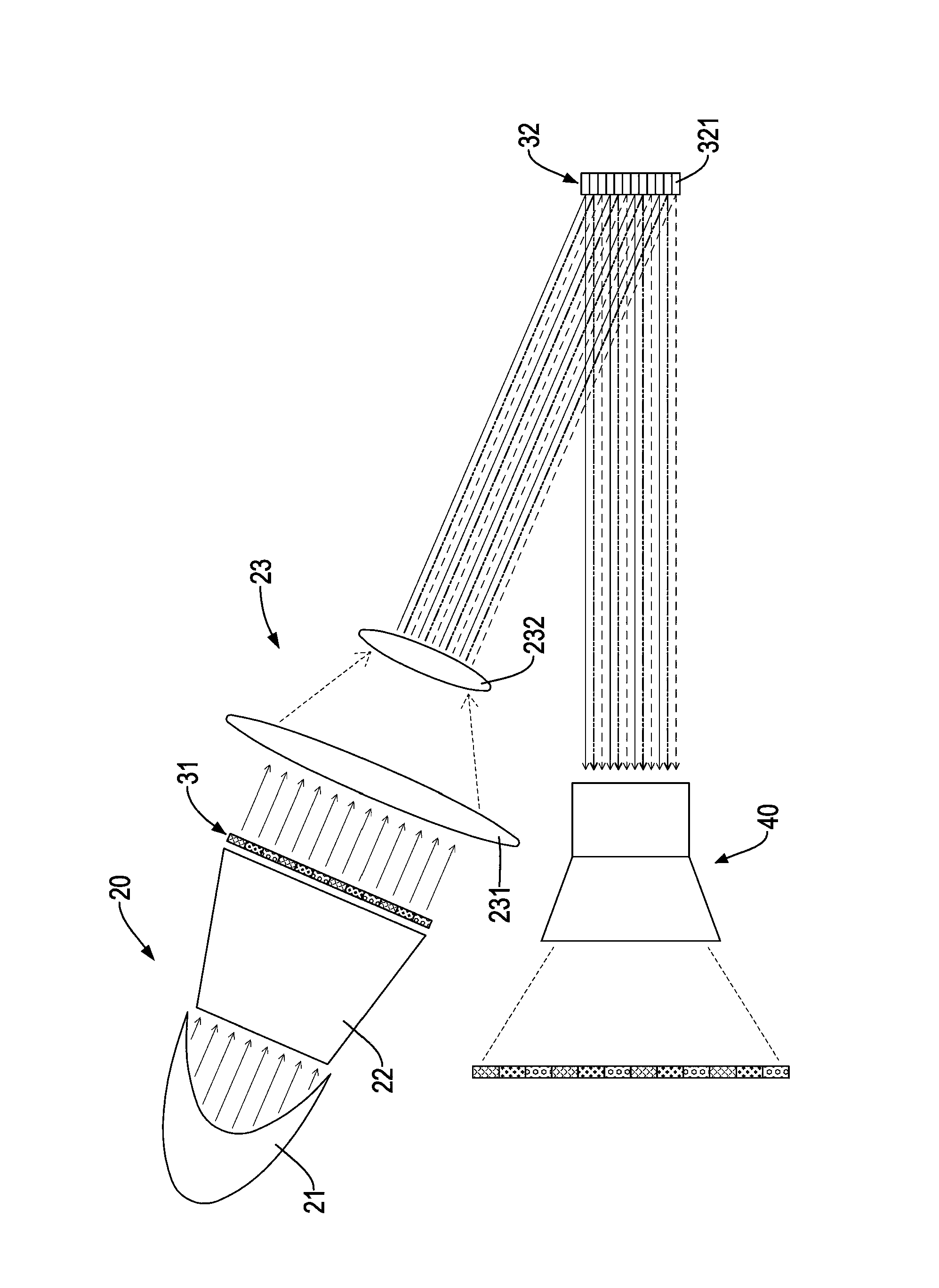
[0024] like figure 1 and image 3 As shown, the present invention relates to a direct image output device, including a housing (not shown), a light source group 20 accommodated in the housing, a digital microcomputer set in the housing and used to receive the light source group 20 A chip device 30 (Digital Micro-mirror Device, DMD for short) and a projection lens 40 (Projection Lens) arranged in the housing for outputting light source, wherein:

[0025] The light source group 20 is provided with a light source 21, a light guide column 22 and a miniature lens group 23, the light guide column 22 is used to receive the light source 21, so as to guide the divergent light source 21 into a parallel output light source 21, and the The microlens 23 is used to receive t...


PUM


Abstract

The invention discloses an image direct output device. The image direct output device comprises an outer shell, a light source set, a digital microchip device and a projecting lens. The light source set is provided with a light source, a light guiding column and a miniature lens set. The digital microchip device is used for collecting miniature light beams of the light source set and is provided with a stationary-type color wheel and a minitype reflecting mirror set. The stationary-type color wheel is used for conducting color separation and color filtering on the light source and is provided with a plurality of color blocks. The minitype reflecting mirror set is arranged on the side, different from the light guiding column, of the miniature lens set and is used for receiving the light source which is processed by the stationary-type color wheel. The projecting lens is used for receiving an output light source of the digital microchip device and enabling the output light source to be shot out of the outer shell. The image direct output device which can effectively lower needed cost and time is provided.

Description

technical field [0001] The invention relates to a direct output device, especially an image direct output device which can reduce manufacturing cost and time. Background technique [0002] With the rapid development of modern technology, the current digital image projection and display industry has evolved from the three-gun color projection technology with a huge size like a desktop in the early stage. So far, there are simple projectors and single-gun projectors that are as small as a mobile phone and can be carried around. High image quality and high brightness are suitable for lectures, presentations, or movie watching projectors and home-use large-screen high-contrast (Full HD 1080P) projection TVs, etc. The customer base of these digital image projection and display products also comes from a few specific companies The office needs instruments and gradually expands to household consumer electronics products, which are widely used in a large number of applications; [...

Claims


Application Information

Patent Timeline
Patent Type & Authority Applications(China)
IPC IPC(8): G03B21/20G03B21/14G02B7/00
Inventor 杨进忠萧安廷
Owner BOHHEN OPTRONICS
Why Eureka
Try Eureka