Automatic matching method for radio frequency channels of multichannel distributed antenna system

A technology of distributed antennas and radio frequency channels, which is applied in the field of automatic matching of radio frequency channels in multi-channel distributed antenna systems, can solve the problems of poor scalability and fixed channels, etc. The effect of business multi-standard mobile signal transmission and coverage

Active Publication Date: 2013-11-06
SUNWAVE COMM
View PDF6 Cites 25 Cited by
  • Summary
  • Abstract
  • Description
  • Claims
  • Application Information

AI Technical Summary

Problems solved by technology

[0003] However, most of the existing digital distributed antenna systems are customized according to the frequency band of the operator. The frequency and bandwidth of each channel of the access unit are fixed, and the remote unit corresponds to the access unit, and the channel is also fixed.
The advantage of this structure is that it is simple to implement, but the scalability is poor
If the application environment changes, it is necessary to change the standard of a certain source (the frequency band and bandwidth of the source may change), or a new frequency band is put into use (such as the need to access LTE signals in the original system), this system is completely Unable to meet new requirements, only the entire system can be replaced

Method used


Image

  • Automatic matching method for radio frequency channels of multichannel distributed antenna system
  • Automatic matching method for radio frequency channels of multichannel distributed antenna system
  • Automatic matching method for radio frequency channels of multichannel distributed antenna system

Examples


Embodiment Construction

[0029] The present invention will be further described below in conjunction with accompanying drawing:

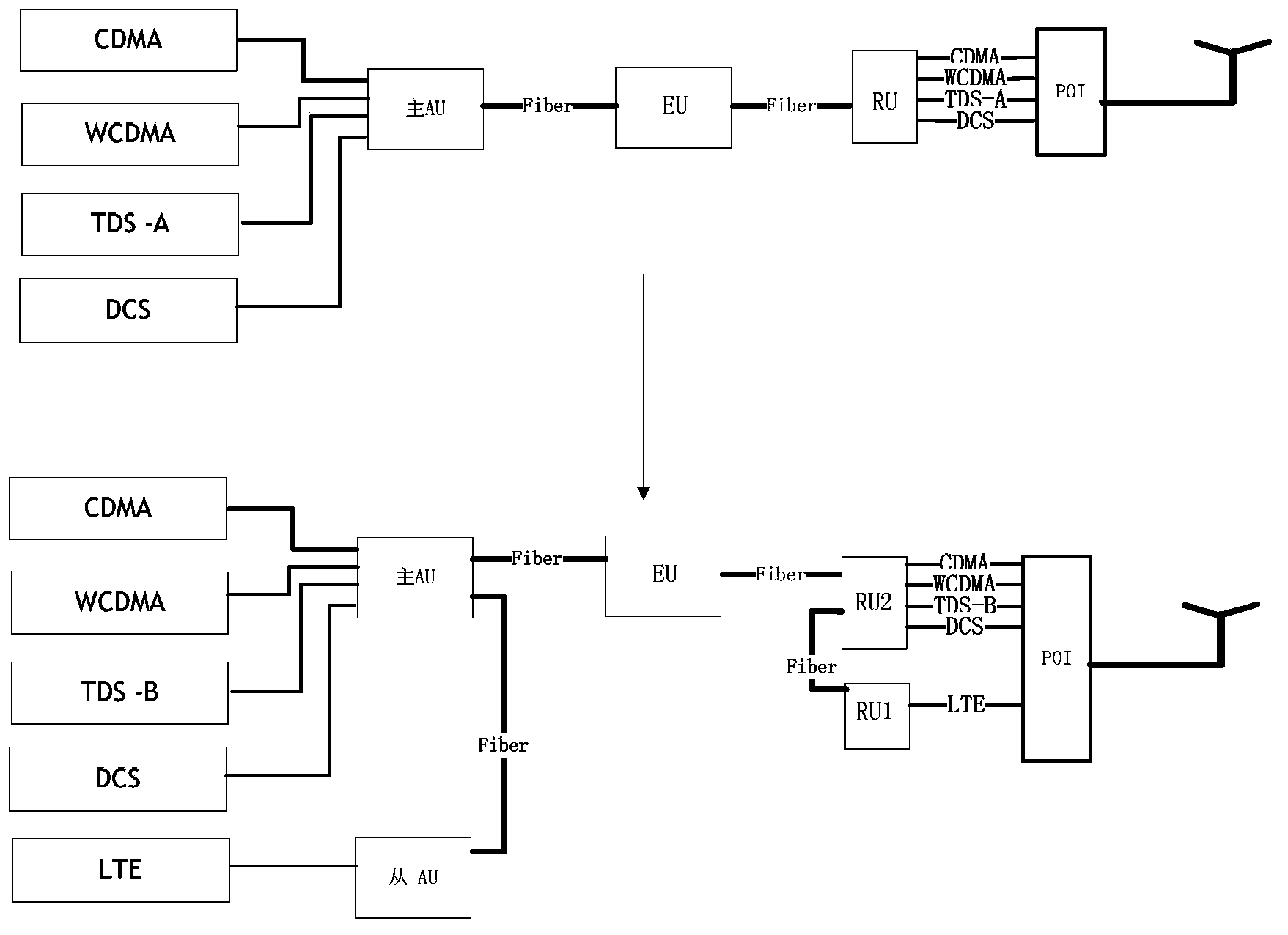
[0030] DAS system networking mode with carrier automatic allocation function, such as figure 1 shown. The access unit (AU) in the system realizes the base station signal access, converts the analog signal into a digital signal, and sends it to the extension unit (EU) through the digital optical fiber after framing; the EU forwards the digital signal from the AU to multiple remote coverage Unit (RU); RU finally achieves signal amplification and coverage. AU, RU and EU are connected through digital optical fiber. In addition to transmitting digital baseband data, the optical fiber also needs to transmit control data of Ethernet protocol. The main AU can establish a TCP / IP or UDP connection with any sub-device in the system. Interactive configuration parameters.

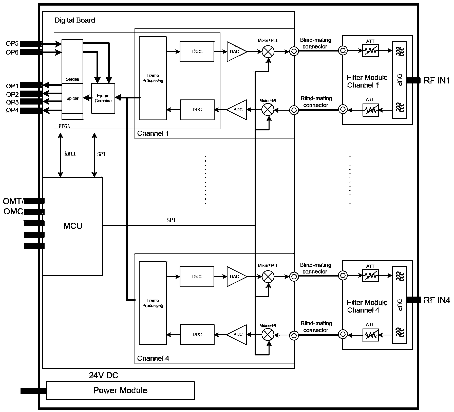
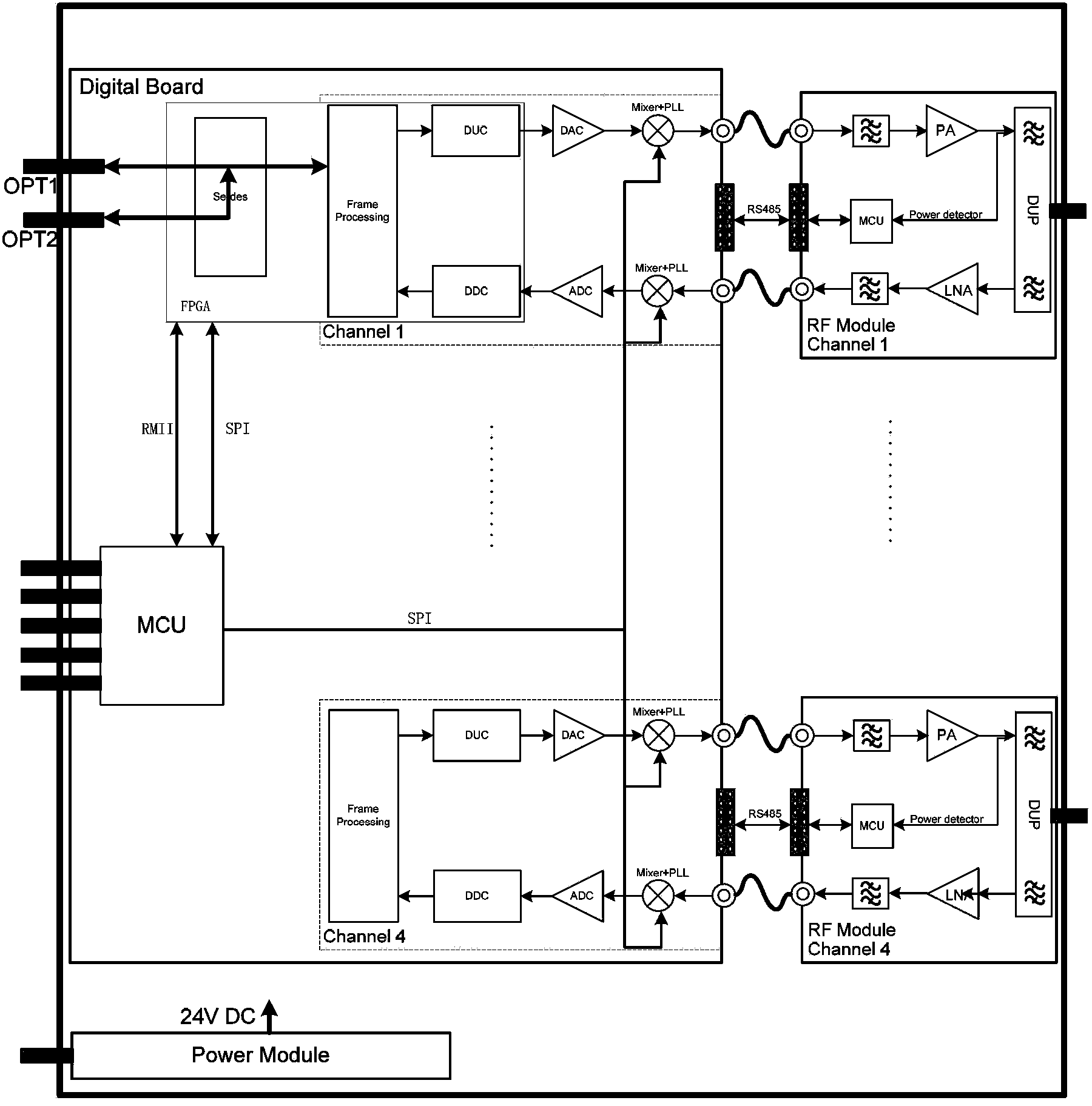
[0031] AU internal structure such as figure 2 As shown, it is mainly composed of power module, digital board,...


PUM


Abstract

The invention provides an automatic matching method for radio frequency channels of a multichannel distributed antenna system. The automatic matching method for the radio frequency channels of the multichannel distributed antenna system comprises steps of diving optical fiber transmission resources into a plurality of signal transmission units which have fixed bandwidth and mapping to any radio frequency channel; setting up a carrier wave information chart through a main AU (Access Unit) according to configuration information of the radio frequency channels and sending the information chart to all RUs (Remote Units); setting up a mapping list of main AU radio frequency channels and the signal transmission units through the main AU according to the carrier wave information chart; setting up a mapping list between auxiliary radio frequency channels and the signal transmission units when the carrier wave information chart is received; setting up a mapping list between the radio frequency channels and the signal transmission units according to the operating frequency band range of a power amplifier module of a local machine and in combination with carrier wave configuration information when the RUs receive the carrier wave information chart form the main AU. The automatic matching method for the radio frequency channels of the multichannel distributed antenna system has the advantages of providing a carrier wave free dispatching method for a multimode and multi-standard DAS (Data Acquisition System), increasing the extendibility of the system and enabling few parts to be changed for a same set of software and hardware system to satisfy networking requirements of various application scenarios.

Description

technical field [0001] The invention relates to a distributed antenna system in the field of mobile communication, and relates to an automatic matching method for radio frequency channels of a multi-channel distributed antenna system. Background technique [0002] Mobile communication technology is developing rapidly, 3G has been used on a large scale, and LTE technology has also begun trial commercial use. In this context, the growth of mobile data services is also showing explosive growth. Since most mobile data services take place indoors, the status of indoor coverage of mobile signals has been significantly improved. The indoor coverage system is no longer just a supplement to outdoor macro base stations like in the 2G era. Traditional indoor coverage mostly uses repeater technology, which has poor scalability and is already difficult to meet the needs of 3G services. As a new generation of room division technology, the digital distributed antenna system has begun to ...

Claims


Application Information

Patent Timeline
Patent Type & Authority Applications(China)
IPC IPC(8): H04B1/18H04L1/06H04B7/06
Inventor 毛建洋李鑫陈青松
Owner SUNWAVE COMM
Why Eureka
Try Eureka