
Method and device for frequency domain equalization detection

A technology of frequency domain equalization and detection methods, which is applied in the communication field, can solve problems such as the decrease of calculation accuracy, the deterioration of detection performance, and the decline of detection performance, so as to achieve the effect of ensuring detection performance

Active Publication Date: 2013-11-06
DATANG MOBILE COMM EQUIP CO LTD
View PDF4 Cites 13 Cited by
  • Summary
  • Abstract
  • Description
  • Claims
  • Application Information

AI Technical Summary

Problems solved by technology

[0018] (4) Received signal model under the condition of inter-cell interference in the uplink of LTE system
[0027] In the prior art, only the MRC detection method or the IRC detection method can be fixedly selected for detection. Through the analysis of the received signal expression, it can be known that when the interference plays a dominant role in the received signal, the MRC detection method only regards the above interference as noise It will inevitably lead to a sharp deterioration of the detection performance; when the interference does not play a dominant role in the received signal, the IRC detection method will lead to a decrease in calculation accuracy due to the introduction of channel estimation errors, and will lead to a decrease in detection performance

Method used


Image

  • Method and device for frequency domain equalization detection
  • Method and device for frequency domain equalization detection
  • Method and device for frequency domain equalization detection

Examples


Embodiment 1

[0046]The downlink of the LTE system adopts OFDMA (Orthogonal Frequency Division Multiple Access, Orthogonal Frequency Division Multiple Access), and the uplink adopts SC-FDMA technology. Each user in the cell is orthogonal to each other and there is no interference. The same frequency band is used between cells, and the interference between cells becomes the main interference. In many practical scenarios, LTE uplink is an interference-limited system, and narrow-band interference may exist in some PRB bandwidths; in interference-limited systems (there are relatively large Strong inter-user interference or co-channel interference caused by frequency reuse), when the interference plays a dominant role in the received signal, the MRC detection method treats the above interference as noise, and the performance of the IRC detection method is better than that of the MRC detection method at this time; When the interference does not play a dominant role in the received signal, the IRC ...

Embodiment 2

[0112] Based on the same inventive concept as the above method, an embodiment of the present invention also provides a frequency domain equalization detection device, such as Figure 4 As shown, the equipment includes:

[0113] The first calculation module 11 is used to calculate the time-domain signal-to-interference-noise ratio SINR of the pilot subcarrier;

[0114] The second calculation module 12 is used to calculate the noise interference covariance matrix Re_pilot of the pilot subcarrier;

[0115] The third calculation module 13 is used to calculate the noise-to-interference ratio NIR by using the noise-interference covariance matrix Re_pilot of the pilot subcarrier;

[0116] The determining module 14 is configured to use the time-domain signal-to-interference-noise ratio SINR and the noise-to-interference ratio NIR to determine that frequency domain equalization detection is performed in an interference suppression combined IRC detection method or a maximum ratio combi...


PUM


Abstract

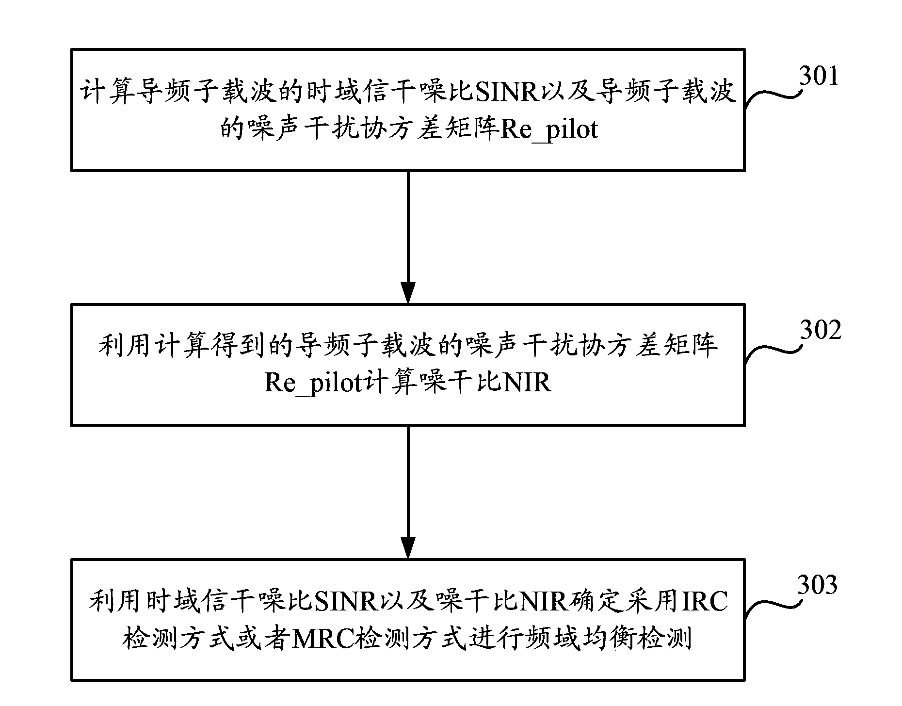
The invention discloses a method and device for frequency domain equalization detection. The method comprises the steps that a time domain signal interference noise ratio (SINR) and a noise interference covariance matrix Re_pilot of a pilot frequency subcarrier are calculated; the noise interference covariance matrix Re_pilot of the pilot frequency subcarrier is utilized for calculating a noise interference ratio (NIR); the time domain SINR and the NIR are utilized for determining the adoption of an interference rejection combining (IRC) detection mode or a maximal ratio combining (MRC) detection mode to conduct the frequency domain equalization detection. According to the method and device for the frequency domain equalization detection, the frequency domain equalization detection is conducted in the mode that the MRC detection mode or the IRC detection mode is selected in a self-adaptive pattern, therefore, when interference plays a leading role in receiving signals, the interference and noise can be distinguished and processed, and the detection performance can be fully guaranteed; when the interference does not play a leading role in receiving the signals, the situation that computational accuracy is lowered due to the introduction of channel estimation errors cannot occur, and therefore the detection performance can be fully guaranteed.

Description

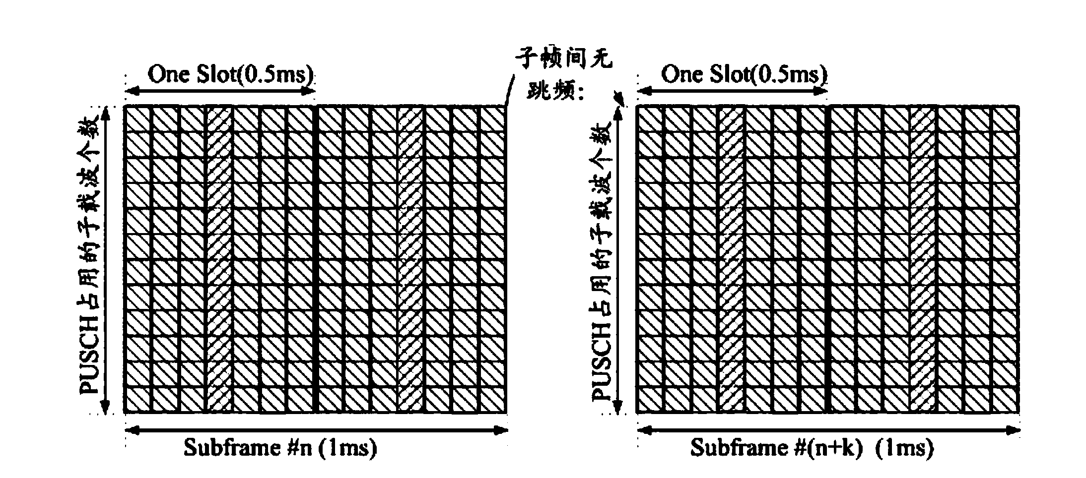
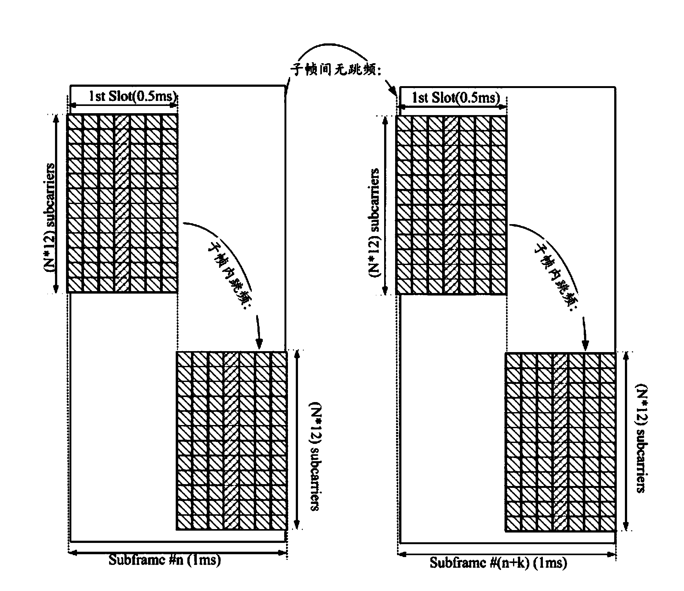
technical field [0001] The present invention relates to the field of communication technology, in particular to a method and equipment for frequency domain equalization detection. Background technique [0002] (1) A time-frequency domain structure of an uplink data signal and a pilot signal of an LTE (Long Term Evolution, long-term evolution) system. [0003] The time-frequency domain structure of PUSCH (Physical Uplink Shared Channel, Physical Uplink Shared Channel) in subframe n is: one subframe (1ms) is occupied in the time domain, and N PRBs (Physical Resource Block, physical resource block) are occupied in the frequency domain , each PRB occupies 12 SCs (Subcarriers) in the frequency domain. Each subframe contains two columns of PUSCH pilots. Under the conventional CP (Cyclic Prefix, cyclic prefix), the PUSCH pilot signal is located in the fourth column SC-FDMA (Single Carrier-Frequency Division Multiple Access, single carrier frequency division multiple access ) symb...

Claims


Application Information

Patent Timeline
IPC IPC(8): H04L25/02H04L25/03H04L27/26
Inventor 任斌李琼戴晓明
Owner DATANG MOBILE COMM EQUIP CO LTD
Learn More