Rotating door capable of generating power

A revolving door and generator technology, applied in the field of revolving doors, can solve problems such as unfavorable environmental protection, polluting gas waste, etc., and achieve the effects of simple structure, energy saving and convenient use.

Inactive Publication Date: 2013-11-13
SHANGHAI ZHABEI DISTRICT HETIANLU PRIMARY SCHOOL
View PDF0 Cites 7 Cited by
  • Summary
  • Abstract
  • Description
  • Claims
  • Application Information

AI Technical Summary

Problems solved by technology

[0004] Moreover, at present, most of the various generators need to consume coal, petroleum, diesel, gasoline and other energy, and burn them to drive the main shaft of the generator, so as to drive the generator to do work through the main shaft to gen

Method used


Image

  • Rotating door capable of generating power

Examples


Embodiment Construction

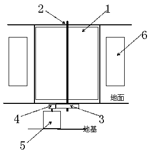
[0013] The invention provides a revolving door capable of generating electricity. The meshing of large and small gears is used as a transmission mechanism to transmit the kinetic energy generated by the inertial rotation of the revolving door to the generator to achieve the purpose of generating electricity.

[0014] Referring to the accompanying drawings, the revolving door capable of generating electricity of the present invention will be introduced and described in detail through specific embodiments, so as to better understand the content of the present invention, but it should be understood that the following embodiments do not limit the scope of the present invention.

[0015] refer to figure 1 , the revolving door capable of generating electricity in the present invention includes a revolving door body 1 , a central shaft 2 of the revolving door, a large gear 3 , a pinion 4 , a generator 5 , and several light emitting diodes 6 .

[0016] Wherein, in addition to the revo...


PUM


Abstract

The invention provides a rotating door capable of generating power. Meshing between a bull wheel and a pinion is used as a transmission mechanism; kinetic energy produced by inertia rotation of the rotating door is conducted to a power generator, so that the aim of generating the power is fulfilled; energy saving and emission reduction can be effectively realized; and moreover, the rotating door is simple in structure and convenient to use.

Description

technical field [0001] The invention relates to a power generating device, in particular to a revolving door capable of generating power. Background technique [0002] Nowadays, with the development of science and technology and the progress of society, revolving doors are widely used in the entrance and exit systems of major restaurants, airports, large shopping malls, hospitals, merchant clubs, hotels, office buildings, and large buildings. Generally, a revolving door includes three major components, namely a fixed frame, a rotating assembly and a central axis assembly. Among them, the fixed frame is the frame of the revolving door, which is the part that supports the full load of the bearing on the revolving door; the rotating assembly is composed of the door closer, exhibition box, revolving ceiling and door assembly, which is used for opening and closing the door; the central axis assembly is The drive system of the revolving door is mainly composed of a central shaft,...

Claims


Application Information

Patent Timeline
IPC IPC(8): E06B3/90F03G5/00H02K7/10H02J7/32
Inventor 郑心星
Owner SHANGHAI ZHABEI DISTRICT HETIANLU PRIMARY SCHOOL
Why Eureka
Try Eureka