

Light guide plate and manufacturing method thereof
A manufacturing method and technology of light guide plates, which are applied in the field of light guide plates, can solve the problems of limited design and development of light guide plates, influence of light guide plates on the flatness of light guide plates, and impact on thinning of light guide plates, and achieve cost saving and good flatness effects
- Summary
- Abstract
- Description
- Claims
- Application Information
AI Technical Summary
Problems solved by technology
Method used
Image

Examples
Embodiment Construction
[0013] The light guide plate and the manufacturing method of the light guide plate of the present invention will be further described in detail below with reference to specific implementation methods and drawings.
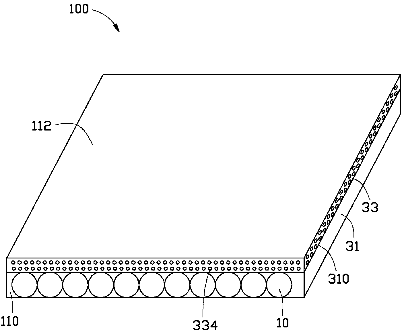
[0014] see figure 1 , figure 1 It is a light guide plate 100 according to an embodiment of the present invention. The light guide plate 100 includes an optical fiber plate 31 and a diffusion layer 33 . The optical fiber plate 31 is formed by bonding a plurality of optical fibers 10 side by side. The optical fiber 10 can be a plastic optical fiber or a glass optical fiber. The fiber optic plate 31 has a surface 310 on which the diffusion layer 33 is located. The diffusion layer 33 is composed of polymer colloid and diffusion particles 334 inside the polymer colloid.
[0015] The particle size of the diffusion particle 334 is between 0.1-200um. The diffusion layer 33 includes a light exit surface 112 , which is the light exit surface 112 of the light guide plate ...
PUM
| Property | Measurement | Unit |
|---|---|---|
| Particle size | aaaaa | aaaaa |
Abstract
Description
Claims
Application Information