

GOA (gate driver on array) circuit, array substrate, display device and driving method
A circuit and input terminal technology, which is applied in the fields of GOA circuits, display devices, and array substrates, can solve the problems of many transistors and large array substrate areas, and achieve the effect of area reduction
- Summary
- Abstract
- Description
- Claims
- Application Information
AI Technical Summary
Problems solved by technology
Method used
Image

Examples
Embodiment 1
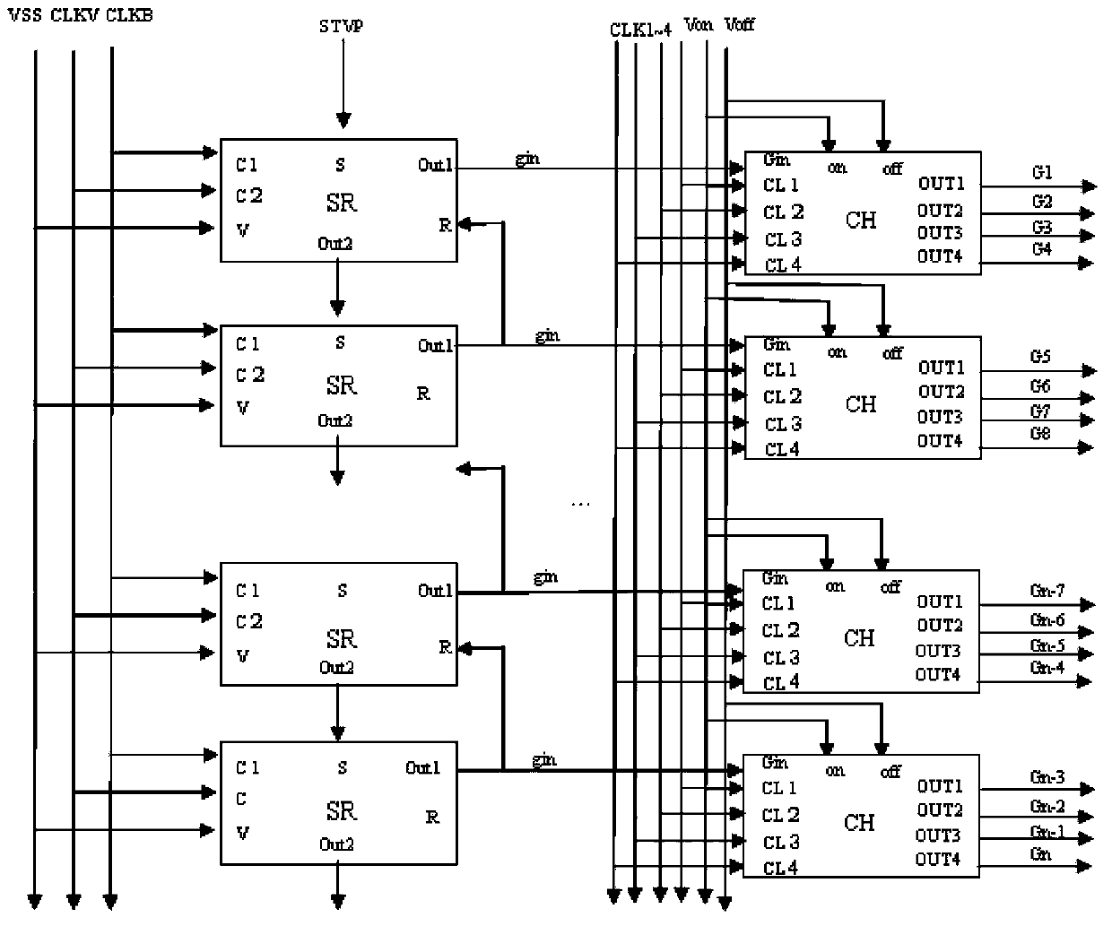
[0092] The selection signal output subunit is used to receive a source signal and output a selection signal according to the source signal;
[0093] The selection subunit receives the selection signal and N clock signals, and outputs the received clock signal according to the selection signal;
[0094] There are at least N clock signal input lines for inputting clock signals to the selection subunits.
[0095] The internal structure of the selection signal subunit can be composed of a GOA unit connected by 12 transistors and a capacitor, or an SRC cascaded register composed of thin film transistors;
[0096] The selection subunit receives N clock signals, and under the control of the selection signals, decides whether to output clock signals, and these clock signals are input to the gate lines of the array substrate where the GOA circuit is located, and the gate lines are based on the The high and low levels of the clock signal turn on or off the switch (usually a thin film t...
Embodiment 2
[0102] The selection signal output subunit includes a source signal input terminal 1, a source signal input terminal 2, a start signal input terminal, a signal output terminal 1, a signal output terminal 2, and a reset signal input terminal;
[0103] The source signal input terminal is used for inputting a first source signal;
[0104] The second source signal input terminal is used to input a second source signal;
[0105] The signal output end is connected to the selection subunit for outputting a selection signal generated according to the first source signal and the second source signal;
[0106] The start signal input end of the first GOA unit is connected to the start signal line to receive the start signal, and the reset signal input end of the first GOA unit is connected to the signal of the second GOA unit. The output terminal one is connected to receive the selection signal output by the signal output terminal one of the second GOA unit;
[0107] The start signal i...
Embodiment 3
[0113] The N clock signal input terminals are respectively connected to the N clock signal input lines for inputting clock signals;
[0114] The selection signal input terminal is used to receive the selection signal output by the selection signal output subunit;
[0115] The clock signal output end outputs the received clock signal according to the selection signal.
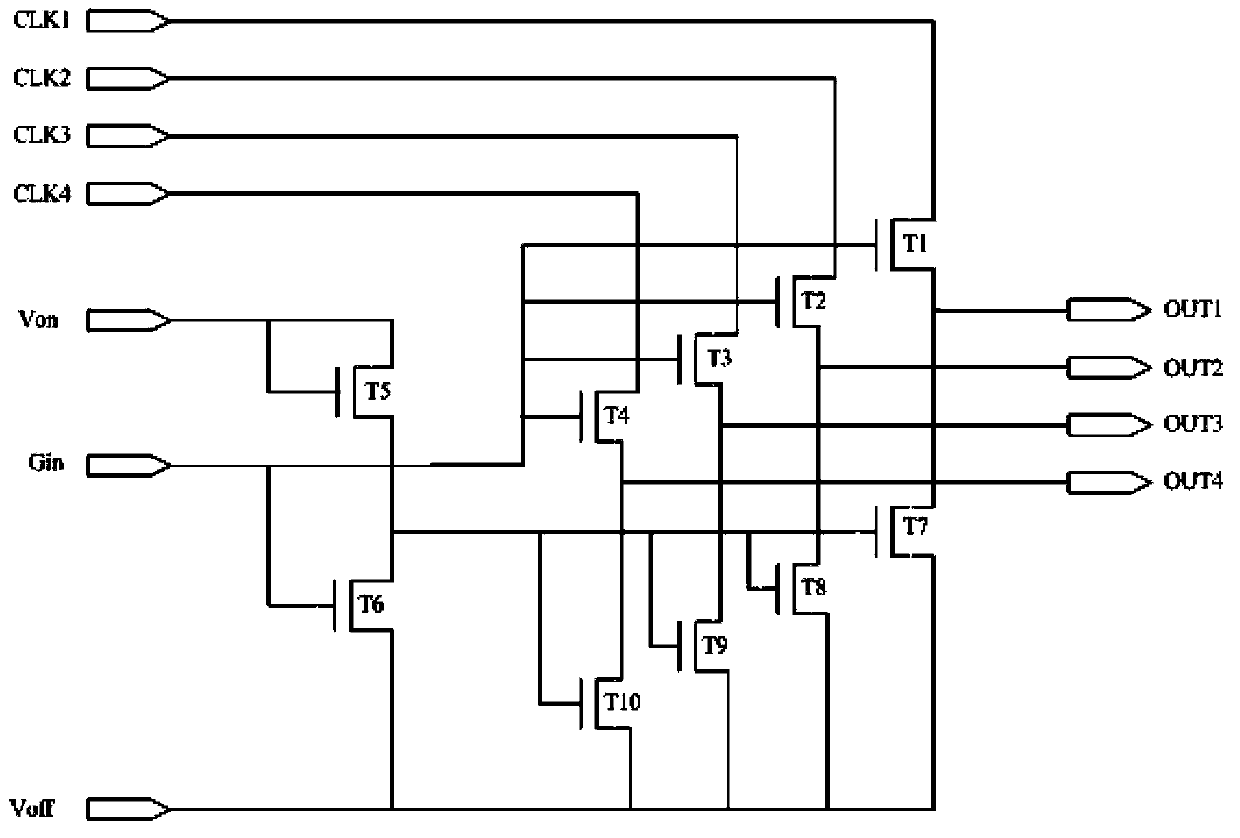
[0116] Such as figure 1 As shown, as a further embodiment of this embodiment:
[0117] The N=4;
[0118] The GOA unit also includes a gate line on voltage line and a gate line off voltage line; the gate line on voltage Von is always high level, and the gate line off voltage Voff is always low level;
[0119] The selection subunit includes a pull-up module, a holding module, a gate-line on-voltage input terminal connected to the gate-line on-voltage line, and a gate-line off-voltage input terminal connected to the gate-line off-voltage line ;
[0120] The pull-up module includes a first transistor T1, a seco...
PUM
 Abstract
Description
Claims
Application Information