
A method for controlling the stability of the output current of a laser drive circuit in the power-on stage

A driving circuit and output current technology, which is applied in the field of controlling the output current stability of the laser driving circuit during the power-on phase, can solve the problems of inconsistent chip power-on time, insufficient power-on driving ability, etc., so as to solve the problem of insufficient driving ability and improve reliability. and stability, the effect of reducing power consumption

Active Publication Date: 2015-12-09
BEIJING MXTRONICS CORP +1
View PDF5 Cites 0 Cited by
  • Summary
  • Abstract
  • Description
  • Claims
  • Application Information

AI Technical Summary

Problems solved by technology

[0005] The purpose of the present invention is to overcome the above-mentioned deficiencies of the prior art, and provide a method for controlling the output current stability of the laser drive circuit in the power-on stage, which solves the problem of insufficient power-on drive capability when the laser drive circuit outputs a large current Does not increase the power consumption of the chip under stable working conditions; solves the current oscillation problem caused by the inconsistent power-on time of the chip between different batches, and improves the reliability and stability of the output current during power-on

Method used


Image

  • A method for controlling the stability of the output current of a laser drive circuit in the power-on stage
  • A method for controlling the stability of the output current of a laser drive circuit in the power-on stage
  • A method for controlling the stability of the output current of a laser drive circuit in the power-on stage

Examples


Embodiment Construction

[0027] The present invention will be further described in detail below in conjunction with the accompanying drawings and specific embodiments.

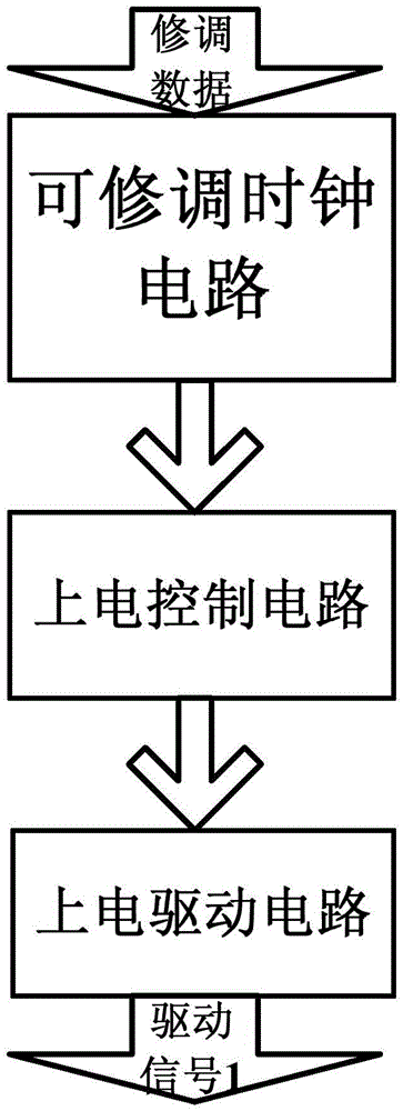
[0028] The method for controlling the output current stability of the laser drive circuit in the power-on stage of the present invention is realized by the power-on module on the laser drive circuit, such as figure 1 Shown is the working principle diagram of the power-on module of the present invention. It can be seen from the figure that the power-on module includes an adjustable clock circuit, a power-on control circuit and a power-on drive circuit.

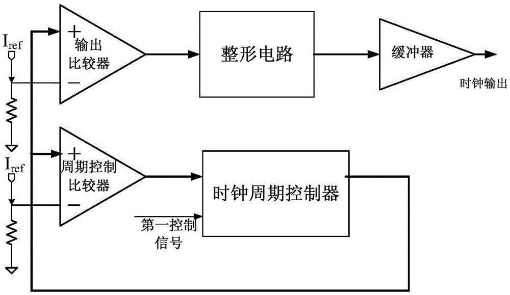
[0029] Such as figure 2 Shown is a schematic structural diagram of the adjustable clock circuit in the power-on module of the present invention. It can be seen from the figure that the adjustable clock circuit includes an output comparator, a cycle control comparator, a shaping circuit, a buffer, and a clock cycle controller. The output comparator is The phase input terminal is conne...


PUM


Abstract

The invention relates to a method for controlling stability of output currents at the power-on stage of a laser driving circuit. Current stability controlling is achieved through a power-on module of the laser driving circuit. The power-on module comprises a trimmable clock circuit, a power-on control circuit and a power-on driving circuit. The method improves period consistency of different chip clock circuits by aid of the digital trimming technology; controls the power-on time of the power-on driving circuit by aid of the power-on control circuit; drives a back end circuit through the power-on driving circuit, constructs a feedback loop and forms the stable control state. The method effectively improves consistency of power-on time of different laser driving circuits, and solves the problem of output current oscillating due to power-on time difference during parallel-connection application of multiple driving chips. The driving mode that the control circuit to control the driving circuit is introduced, the driving circuit is set to be in the low power consumption state after the circuits are stabilized, and therefore power consumption of the whole chip in the stable working period is reduced.

Description

technical field [0001] The invention relates to a method for controlling the output current stability of a laser drive circuit in the power-on stage, and belongs to the technical field of laser drive circuits. Background technique [0002] The monolithic integrated laser driver circuit provides a specified high current for the off-chip laser. The larger the output current, the greater the drive capability required during the chip startup and power-on process, and the more difficult the startup process. At this stage, the output current level of the single-chip integrated laser driver circuit is at the level of 100 milliamperes, and a very high driving capability is required during the power-on process. It takes time to reach the rated driving current, which makes the entire photoelectric system unable to work normally. [0003] In order to provide sufficient driving capability during power-on, the power consumption of the driving circuit is generally high. However, the dr...

Claims


Application Information

Patent Timeline
Patent Type & Authority Patents(China)
IPC IPC(8): H01S5/042
Inventor 陈飞祥王宗民孔瀛王金豪彭新芒管海涛王立果侯贺刚
Owner BEIJING MXTRONICS CORP
Learn More