
Tie bar for supporting system in high-rigidity integral prestressed fabricated foundation pit support

A foundation pit support and support system technology, applied in the direction of infrastructure engineering, excavation, construction, etc., can solve the problems of non-reusable, low support rigidity, difficult to control deformation, etc., to reduce corrosion, ensure safety, ensure The effect of intensity

Inactive Publication Date: 2013-11-20
浙江博雷重型机床制造有限公司
View PDF6 Cites 4 Cited by
  • Summary
  • Abstract
  • Description
  • Claims
  • Application Information

AI Technical Summary

Problems solved by technology

Since the steel support structure currently used mainly uses a single section steel or steel pipe as a support beam, there is no effective connection between each section steel or steel pipe, and it cannot work as a composite structure, so their support stiffness is relatively low. The force it can withstand is relatively limited. For foundation pits with large spans, it is difficult to control their deformation with the current steel support support
Because many of these supports are made according to the requirements of on-site construction, there is no standardized connection size, and the purpose of interchangeability and universal use between various parts cannot be achieved. After the foundation pit construction is completed, most of the support parts have become disposable consumables. , cannot be reused

Method used


Image

  • Tie bar for supporting system in high-rigidity integral prestressed fabricated foundation pit support
  • Tie bar for supporting system in high-rigidity integral prestressed fabricated foundation pit support
  • Tie bar for supporting system in high-rigidity integral prestressed fabricated foundation pit support

Examples


Embodiment 1

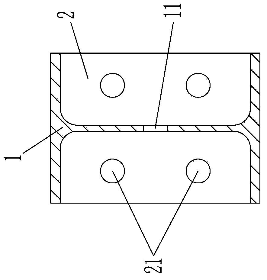
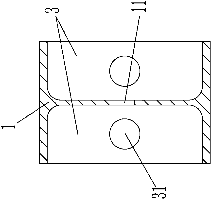
[0015] like figure 1 , figure 2 , image 3 , Figure 4 The tie rods for the high-rigidity overall prestressed assembled foundation pit support inner support system shown include long rod-shaped H-shaped steel 1, and the two ends of the H-shaped steel 1 are welded and fixed to a rectangular flange plate 2, and the flange plate 2 is fixed. Four connection holes 21 are provided, and the four connection holes 21 are divided into two rows up and down, and each row is set up one above the other. Two to four lug plates 3 are arranged in the side groove of the H-shaped steel 1, and the rectangular suspension The three sides of the lug plate 3 are respectively welded and fixed to the web plate and the wing plate of the H-shaped steel 1. The lug plate 3 has a hanging hole 31. The side groove of the H-shaped steel 1 is divided into multiple sections by the lug plate 3. Each section At least one drainage hole 11 is opened on the web of the H-shaped steel 1 .

[0016] In this embodime...


PUM


Abstract

The invention discloses a tie bar for a supporting system in a high-rigidity integral prestressed fabricated foundation pit support. The tie bar comprises a long-bar-shaped H-beam, rectangular flange plates are welded and fixed at two ends of the H-beam, four connecting holes are formed in each flange plate and divided into an upper row and a lower row, the two connecting holes in each row are in up-down one-to-one correspondence, two to four lifting lug plates are arranged in side grooves of the H-beam, three edges of each rectangular lifting lug plate are welded and fixed with a web and flanges of the H-beam respectively, and each lifting lug plate is provided with a lifting hole. Each side groove of the H-beam is partitioned into multiple sections by the lifting lug plates, and at least one drain hole is formed in the web of the H-beam in each section. According to the technical scheme, holes in standard assembling sizes are designed to be connected with other angle braces, diagonal braces or columns, the drain holes are provided so as to achieve the purpose of water draining in rainy days or construction environments with water, corrosion to parts is reduced, and the lifting lug plates are arranged for the convenience of lifting and can be used repeatedly.

Description

technical field [0001] The invention relates to a high-rigidity overall prestressed assembly type foundation pit support internal support system, in particular to a tie rod used for a high-rigidity integral prestressed assembly type foundation pit support internal support system. Background technique [0002] In soft soil deep foundation pit engineering, reinforced concrete or steel pipe supports the support structure. In order to reduce the deformation of the foundation pit and increase the stability, the commonly used methods are: increase the size of the reinforced concrete purlin street surface, increase the number of steel pipe supports, Reduce spacing etc. But this will greatly increase the consumption of building materials and also reduce the effective construction space in the foundation pit. Since the steel support structure currently used mainly uses a single section steel or steel pipe as a support beam, there is no effective connection between each section steel...

Claims


Application Information

Patent Timeline
Patent Type & Authority Applications(China)
IPC IPC(8): E02D17/02E02D17/04
Inventor 高尔荣
Owner 浙江博雷重型机床制造有限公司
Learn More