Method for detecting bed boundary

A technology of formation interface and logging tools, which is applied in the directions of measurement, earthwork drilling and production, boreholes/well components, etc. It can solve the problems that directional resistivity measurement tools cannot meet the work needs, so as to improve practicability, ensure efficiency, and avoid vibrate or shake effect

Inactive Publication Date: 2013-11-20
CNPC GREATWALL DRILLING ENG
View PDF8 Cites 11 Cited by
  • Summary
  • Abstract
  • Description
  • Claims
  • Application Information

AI Technical Summary

Problems solved by technology

[0009] The purpose of the embodiments of the present invention is to provide a method for detection of formation boundaries to solve the problem that the directional resistivity measurement tool cannot meet the needs of actual work

Method used


Image

  • Method for detecting bed boundary
  • Method for detecting bed boundary
  • Method for detecting bed boundary

Examples


Embodiment Construction

[0035] Hereinafter, the present invention will be described in detail with reference to the drawings and examples. It should be noted that, in the case of no conflict, the embodiments in the present application and the features in the embodiments can be combined with each other.

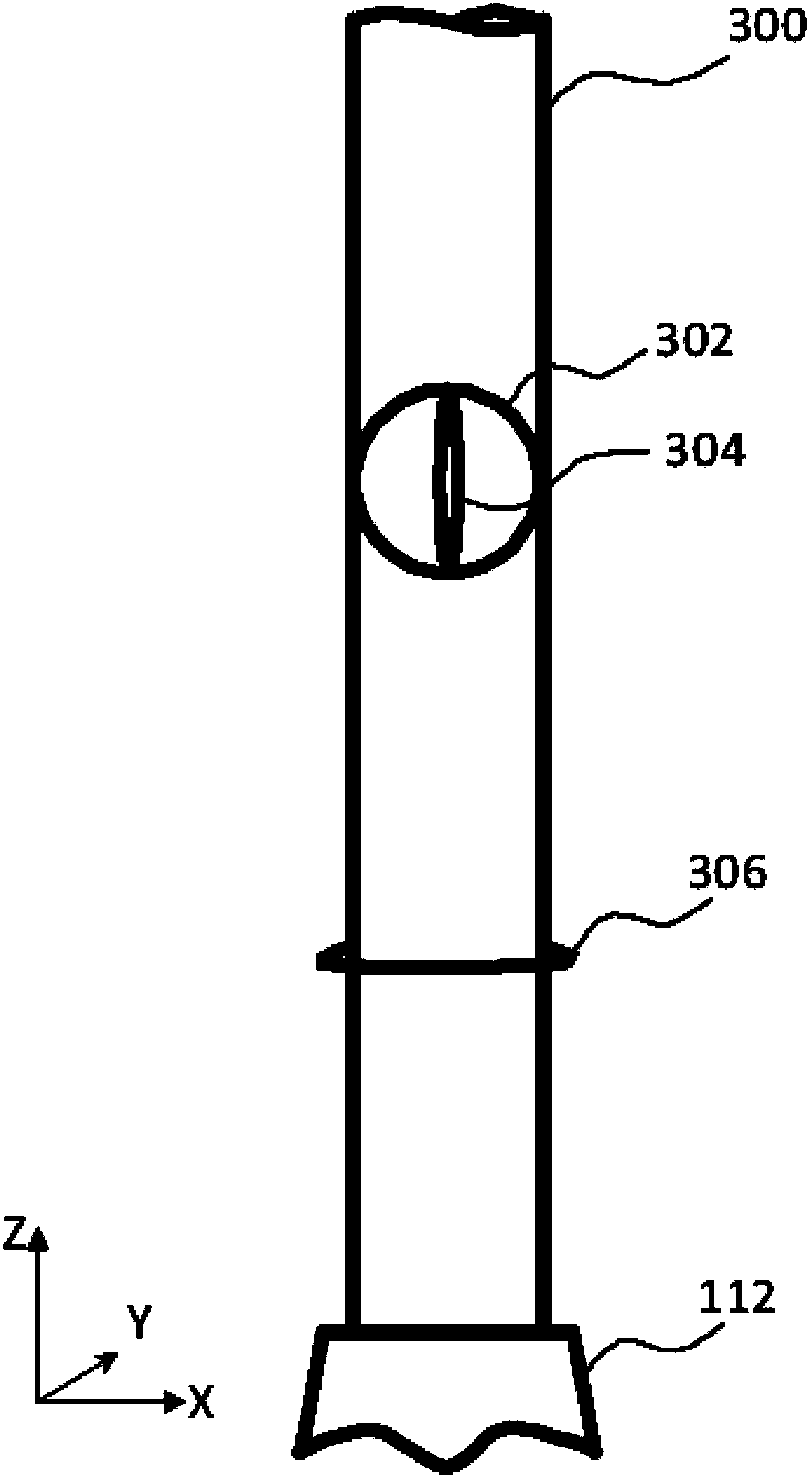
[0036] Figure 3A It is the front view of the directional resistivity measurement tool in the example of the present invention. A directional resistivity measurement tool may include a tool housing 300, two transmitters with x- and y-axes: an x-transmitter 304 and a y-transmitter 302, a receiver with a z-axis: a z-receiver machine 306, and the drill bit 112 at the distal end of the tool housing 300. A coordinate system (x, y, z) associated with the tool housing 300 . The direction of the longitudinal axis of the tool housing 300 is defined as the Z-axis of the current coordinate system (x, y, z). The x-transmitter 304, y-transmitter 302, and z-receiver 306 may include one or more antennas for tra...


PUM


Abstract

The invention discloses a method for detecting a bed boundary. The method includes the steps that a tool shell with a longitudinal axis is placed in a borehole, wherein a first transmitter, a second transmitter and a receiver are configured on the tool shell, and the directions of the devices are different; the magnetic torque of electromagnetic signals transmitted by the first transmitter and the second transmitter is modulated, then, the first transmitter and the second transmitter are made to send the electromagnetic signals at the same time, and total magnetic torque vectors of the electromagnetic signals are electrically rotated in the transmitting process; the receiver is used for receiving and measuring the modulated electromagnetic signals transmitted by the first transmitter and the second transmitter, and then the amplitude and the phase positions of the modulated electromagnetic signals are acquired; the direction and the position of the bed boundary are calculated according to the amplitude and the phase positions measured and acquired by the receiver. According to the method, the problem that a tool for measuring the directional resistivity can not meet practical work requirements is solved, and practicability of the devices is improved.

Description

technical field [0001] The present invention mainly relates to electrical logging in oil wells. In particular, the present invention relates to a method for formation boundary detection. Background technique [0002] Gathering downhole information typically uses electrical measurement methods such as logging while drilling (“LWD”), measurement while drilling (“MWD”), and wireline logging systems. Well known in the oil industry, these techniques have long been used to obtain downhole information, for example, using formation resistivity (or conductivity; the terms "resistivity" and "conductivity", although opposite in meaning, are used interchangeably in the art) and dielectric constant determine the petrophysical properties of the formation and the liquid it contains. The collected downhole information can help characterize hydrocarbons (such as crude oil or natural gas) in porous formations and reflect other conditions to identify formation boundaries between different fo...

Claims


Application Information

Patent Timeline
IPC IPC(8): E21B47/00E21B49/00
Inventor 刘乃震赵齐辉卢毓周李永和白锐刘策李敬翁波强
Owner CNPC GREATWALL DRILLING ENG
Why Eureka
Try Eureka