
Engine heat management electromagnetic speed regulation energy-saving fan system

A technology of electromagnetic speed regulation and fan system, applied in engine components, machine/engine, engine cooling, etc., can solve the problems of low temperature control accuracy, high power consumption, poor heat dissipation effect, etc.

Inactive Publication Date: 2013-11-20
WUXI CHUANGCHEN TECH
View PDF8 Cites 3 Cited by
  • Summary
  • Abstract
  • Description
  • Claims
  • Application Information

AI Technical Summary

Problems solved by technology

[0002] In order to further save energy for the engine and improve engine efficiency, the heat dissipation of the car radiator has changed from the traditional first-generation cooling fan connected to the engine, and the fan will run and consume energy as long as the engine starts, and gradually developed to the second generation. Silicon oil clutch is installed before the cooling fan heats up. , using the principle of thermal expansion and contraction of silicone oil, the fan does not run at low temperature, and starts to run and dissipate heat when the water temperature of the water tank rises to a predetermined temperature, which achieves a certain energy-saving effect. However, due to the silicone oil clutch, there are disadvantages such as low temperature control accuracy and easy oil leakage. At present, the third generation is gradually developing an electromagnetic fan clutch in front of the cooling fan, using a temperature control switch and a controller to control the operation of the fan. The disadvantages are that the fan is noisy and the heat dissipation effect is poor when running at low speed in summer.
Now the fourth-generation electronic fan has appeared, which uses four motors, four cooling fans are installed on the four motors, and the controller is used to control the operation and stop of the four fans according to the height of the user to achieve the effect of heat dissipation and energy saving. The advantage is only Trial for new cars, the speed is not affected by the change of engine speed, the disadvantage is that the power consumption is large, the current of the four fan motors is 50-70A, the cost is high, when the old car is refitted due to the large power consumption, it is necessary to replace a larger battery and generator

Method used

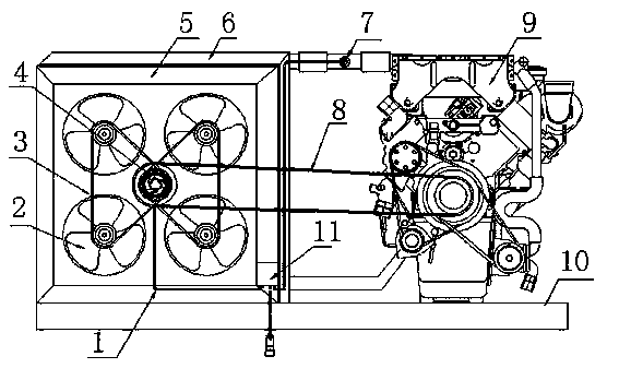

Image

  • Engine heat management electromagnetic speed regulation energy-saving fan system

Examples


Embodiment Construction

[0014] The present invention will be described in detail below in conjunction with the accompanying drawings. The description in this part is only exemplary and explanatory, and should not have any limiting effect on the protection scope of the present invention.

[0015] Such as figure 1 The shown engine thermal management electromagnetic speed-regulating energy-saving fan system consists of four low-noise and long-life mechanical fans 2, transmission belt 8, electromagnetic speed-regulating clutch 4, fan cover 5, water tank 6, engine 9, clutch transmission belt 3 , a water temperature sensor 7, a clutch controller 11 and a fixed bracket 10, the four fans 2 are symmetrically distributed, and are all connected with the electromagnetic speed regulating clutch 4 through the clutch transmission belt 3; the electromagnetic speed regulating clutch 4 The transmission belt 8 is connected to the engine 9; the electromagnetic speed control clutch 4 is connected to the clutch controller...


PUM


Abstract

The invention discloses an engine heat management electromagnetic speed regulation energy-saving fan system which is composed of four mechanical fans with low noise and long service life, a transmission belt, an electromagnetic speed regulation clutch, fan covers, a water tank, an engine, a clutch transmission belt, a water temperature sensor and a clutch controller. According to the engine heat management electromagnetic speed regulation energy-saving fan system, the shortages that in a existing system in the prior art, a silicone oil clutch is low in control accuracy and high in noise, an electromagnetic fan clutch is high in fault rate and high in noise and an electronic fan is large in power consumption are overcome, the engine heat management electromagnetic speed regulation energy-saving fan system has the advantages of being high in energy utilization, long in service life and high in reliability.

Description

technical field [0001] The invention relates to the technical field of engine heat management systems, in particular to an engine heat management electromagnetic speed-adjustable energy-saving fan system related to heat dissipation of a water tank of the engine heat management system and energy-saving utilization of the engine. Background technique [0002] In order to further save energy for the engine and improve engine efficiency, the heat dissipation of the car radiator has changed from the traditional first-generation cooling fan connected to the engine, and the fan will run and consume energy as long as the engine starts, and gradually developed to the second generation. Silicon oil clutch is installed before the cooling fan heats up. , using the principle of thermal expansion and contraction of silicone oil, the fan does not run at low temperature, and starts to run and dissipate heat when the water temperature of the water tank rises to a predetermined temperature, wh...

Claims


Application Information

Patent Timeline
IPC IPC(8): F01P7/04
Inventor 徐金元兰森林侯日郎袁伟红
Owner WUXI CHUANGCHEN TECH
Learn More