Method for automatically identifying and positioning coordinates of image point of artificial mark in camera calibration control field

A technology for controlling signs and positioning methods, which is applied in image enhancement, image analysis, image coding, etc., and can solve problems such as automatic recognition and high-precision measurement of image square coordinates of difficult mark points, complicated recognition process, and complicated calculation steps.

Inactive Publication Date: 2013-11-20
XIAN UNIV OF SCI & TECH
View PDF2 Cites 22 Cited by
  • Summary
  • Abstract
  • Description
  • Claims
  • Application Information

AI Technical Summary

Problems solved by technology

However, based on the camera calibration of the 3D control field, due to the large number of artificial marker points in the control field and the similar texture characteristics of the marker points, it is difficult to realize the automatic recognition and high-precision measurement of the image square coordinates of the marker points, which directly affects the accuracy and automation of subsequent camera calibration. degree
There are two main methods in the prior art that are similar to this problem: one adopts manual methods to obtain the image square coordinates of control field marker points, and its disadvantage is that the degree of automation and accuracy are low
However, the obvious disadvantages of this process are that the calculation steps are complicated, the positioning accuracy is low, and the automation requirements cannot be met.
For example, in the Schneider coding scheme, the code recognition is recognized by features such as shape, position, and size, but the recognition process is complicated and not easy to implement

Method used


Image

  • Method for automatically identifying and positioning coordinates of image point of artificial mark in camera calibration control field
  • Method for automatically identifying and positioning coordinates of image point of artificial mark in camera calibration control field
  • Method for automatically identifying and positioning coordinates of image point of artificial mark in camera calibration control field

Examples


Embodiment Construction

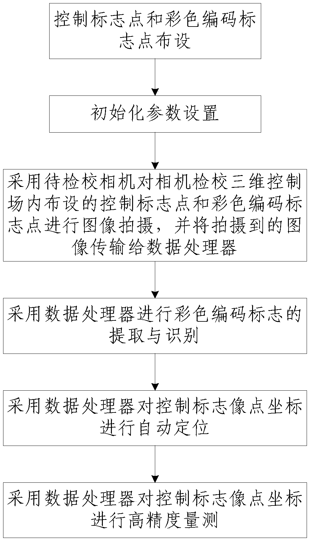
[0063] Such as figure 1 As shown, the method for automatically identifying and locating the image point coordinates of artificial signs in the camera calibration control field of the present invention includes the following steps:

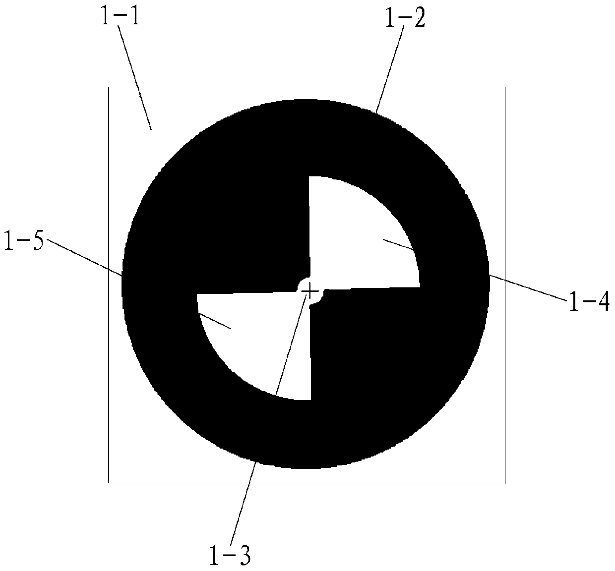
[0064] Step 1. Arrangement of control signs 1 and color-coded signs 2: a plurality of control signs 1 and a plurality of color-coded signs 2 with different codes are arranged in the three-dimensional control field for camera calibration; among them, such as figure 2 As shown, the control sign 1 includes a white base plate 1-1 of the control sign and a black outer circle 1-2 arranged on the white base plate 1-1 of the control sign. The center position of the black outer circle 1-2 is provided with a The black outer circle 1-2 is concentric with the white central circle 1-3, and the two sides of the white central circle 1-3 are provided with a white and mutually symmetrical first fan-shaped 1-4 and a second fan-shaped 1-5. The edge of a sector 1-4 ...


PUM


Abstract

The invention discloses a method for automatically identifying and positioning coordinates of an image point of an artificial mark in a camera calibration control field, which comprises the following steps of 1, arranging a control mark and a color coded mark; 2, setting initialization parameters; 3, adopting a camera to be calibrated to carry out image shooting on the control mark and the color coded mark which are arranged in the camera calibration three-dimensional control field and transmitting a shot image to a data processor; 4, extracting and identifying the color coded mark by adopting the data processing; 5, carrying out automatic positioning on coordinates of an image point of the control mark by adopting the data processor; and 6, carrying out high-accuracy measurement on the coordinates of the image point of the control mark by adopting the data processor. The method has simple steps, is reasonably designed and is convenient to implement; automatic positioning on the control mark can be implemented; extracting efficiency of the control mark is greatly improved; and moreover, the method can achieve higher measurement accuracy and has strong practicality and high popularization and application values.

Description

technical field [0001] The invention belongs to the technical field of camera calibration, in particular to a method for automatically identifying and locating the image point coordinates of artificial signs in a camera calibration control field. Background technique [0002] Non-metric digital camera calibration is one of the key links in photogrammetry and computer vision based on image measurement and three-dimensional measurable reconstruction. The accuracy and reliability of its calibration directly affect the accuracy of subsequent image measurement and spatial positioning measurement . According to whether a control field is needed in the calibration process, non-metric camera calibration can be roughly divided into traditional calibration methods and self-calibration methods based on active vision. The so-called self-checking method based on active vision here does not need to check the reference object, and only uses the image of the surrounding environment during ...

Claims


Application Information

Patent Timeline
Patent Type & Authority Applications(China)
IPC IPC(8): G06T7/00G06T5/00G06T9/00
Inventor 张春森冯鹏飞
Owner XIAN UNIV OF SCI & TECH
Why Eureka
Try Eureka