Magnetic core structure and electromagnetic coupling device based on magnetic core structure

A magnetic core and magnetic column technology, which is applied in the field of electromagnetic coupling, can solve the problems of low energy transmission efficiency, single magnetic field distribution, and low transmission efficiency, and achieve the effects of improving power supply efficiency, simple magnetic core structure, and high transmission efficiency

Active Publication Date: 2013-11-20
GUANGXI POWER GRID ELECTRIC POWER RES INST +1
View PDF8 Cites 30 Cited by
  • Summary
  • Abstract
  • Description
  • Claims
  • Application Information

AI Technical Summary

Problems solved by technology

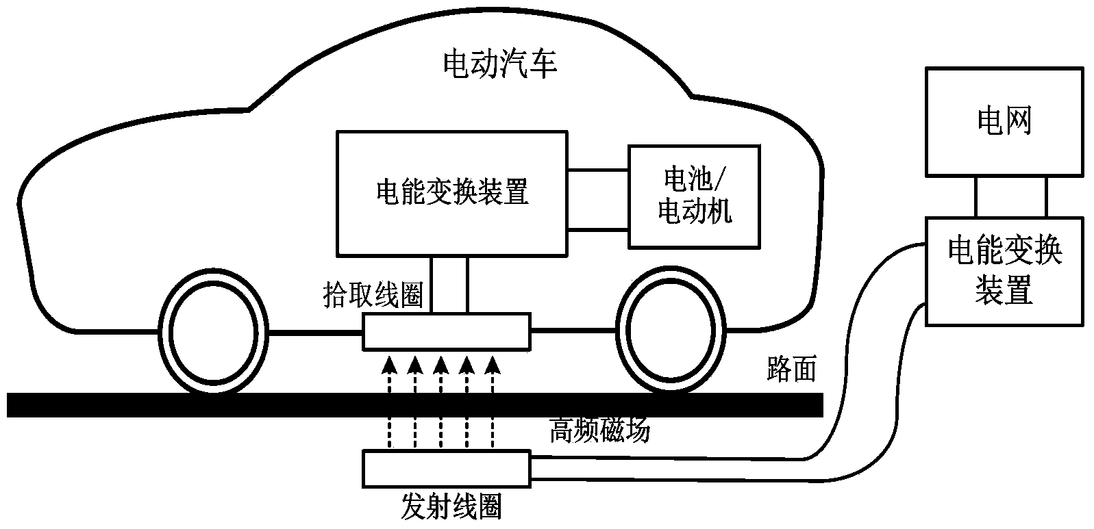
[0004] With this fixed-point charging method, the car must be accurately parked in the preset charging area to ensure accurate alignment between the transmitting coil and the pickup coil, which is very inconvenient to use
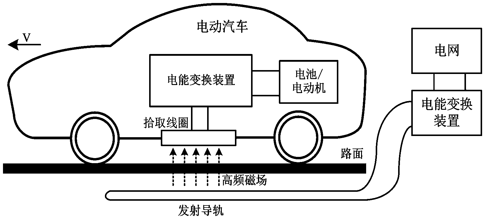
therefore figure 2 Propose a mobile charging method, with figure 1 The difference is that the transmitting coil is set as the transmitting guide rail, and a rather long section of the road is used as the charging area, and a long transmitting guide rail is buried to

Method used


Image

  • Magnetic core structure and electromagnetic coupling device based on magnetic core structure
  • Magnetic core structure and electromagnetic coupling device based on magnetic core structure
  • Magnetic core structure and electromagnetic coupling device based on magnetic core structure

Examples


Embodiment Construction

[0026] The specific implementation manner and working principle of the present invention will be further described in detail below in conjunction with the accompanying drawings.

[0027] Such as Figure 4 As shown, a magnetic core structure includes a transmitting coil core base plate and a pick-up coil core base plate made of ferrite material. The bottom plate of the coil magnetic core and the bottom plate of the pick-up coil magnetic core are arranged relatively parallel, and a plurality of magnetic columns for winding wires are arranged on the inner surface of the magnetic core bottom plate of the transmitting coil, and a “back” shape is opened on the inner surface of the magnetic core bottom plate of the pickup coil. The winding slots, the plurality of magnetic columns on the inner side of the magnetic core bottom plate of the transmitting coil are evenly distributed in a rectangular array.

[0028] Such as Figure 5 , Figure 6 As shown, the multiple magnetic columns o...


PUM

PropertyMeasurementUnit
Notch widthaaaaaaaaaa

Abstract

The invention discloses a magnetic core structure and an electromagnetic coupling device based on the magnetic core structure. The magnetic core structure comprises an emitter coil magnetic core baseplate and a picking coil magnetic core baseplate, which are square and are parallel to each other during working, wherein a plurality of magnetic winding columns are arranged on the inner side surface of the emitter coil magnetic core baseplate and are uniformly distributed in a rectangular array, while winding slots taking the shape of a Chinese character 'hui' are formed in the inner side of the picking coil magnetic core baseplate. The magnetic core structure and the electromagnetic coupling device have the remarkable effects that the structure of the magnetic core is simple, the processing forming is convenient, the magnetic field concentration ability is strong, the radio energy transmission distance is increased, the wound coil can be selectively powered and controlled, the electrical energy transmission area is adjustable to adapt to position deflection of a picking mechanism, the energy dissipation is small and the transmission efficiency is high.

Description

technical field [0001] The invention relates to electromagnetic coupling technology, in particular to a magnetic core structure used in a wireless energy transmission system and an electromagnetic coupling device based on the magnetic core structure. Background technique [0002] Wireless power transfer technology (Inductive Power Transfer), referred to as IPT technology, is a new technology that transfers energy to loads in a non-contact manner through electromagnetic coupling. The electromagnetic coupling mechanism is a key module to realize the wireless transmission of electric energy, and its design is related to various indicators such as the transmission distance, transmission range and transmission efficiency of the IPT system. The electromagnetic coupling mechanism is composed of an energy emitting mechanism and an energy picking mechanism. For mobile devices, their wireless power transmission methods are generally divided into two types: fixed-point transmission an...

Claims


Application Information

Patent Timeline
IPC IPC(8): H01F27/24H01F38/14H02J17/00H02J50/10
Inventor 谢雄威吴丽芳高立克吴智丁祝文姬俞小勇李珊吴剑豪李克文孙跃胡超唐春森王智慧苏玉刚戴欣叶兆虹
Owner GUANGXI POWER GRID ELECTRIC POWER RES INST
Why Eureka
Try Eureka