Method of correcting initial position of rotor of permanent magnet synchronous motor

A technology of rotor initial position and permanent magnet synchronous motor, which is applied in the direction of control of generator, motor generator control, control of electromechanical transmission, etc. It can solve the problems of rotor inability to move, large range of rotor movement, unsafety, etc., and achieve enhanced flexibility performance and immunity, improved position detection accuracy, adjustable frequency and amplitude

Active Publication Date: 2013-11-20
INST OF OPTICS & ELECTRONICS - CHINESE ACAD OF SCI
View PDF7 Cites 16 Cited by
  • Summary
  • Abstract
  • Description
  • Claims
  • Application Information

AI Technical Summary

Problems solved by technology

This type of method has the following problems: due to the existence of friction, especially static friction is often greater than sliding friction, which will cause the rotor to be unable to move if the electromagnetic torque generated by the applied current vector is too small, or the direction of rotation is not obvious. It is easily affected by external disturbance; if the generated electromagnetic torque is too large, the rotor will move too much and the movement time will be too long, which is unsafe in some occasions, and will also affect the rotor when the next current vector acts. direction of movement, resulting in misjudgment

Method used


Image

  • Method of correcting initial position of rotor of permanent magnet synchronous motor
  • Method of correcting initial position of rotor of permanent magnet synchronous motor
  • Method of correcting initial position of rotor of permanent magnet synchronous motor

Examples


Embodiment Construction

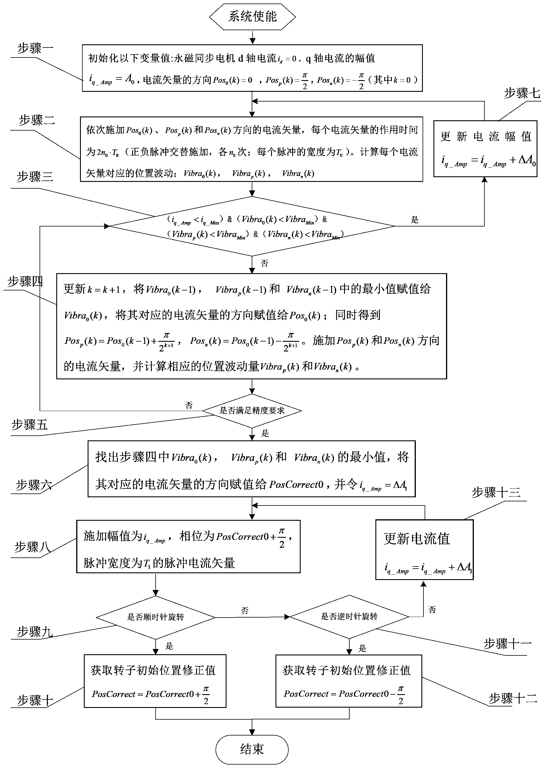
[0031] In order to make the object, technical solution and advantages of the present invention clearer, the present invention will be described in further detail below in conjunction with specific embodiments and with reference to the accompanying drawings.

[0032] combine first figure 2 Introduce the structure of the permanent magnet synchronous motor drive control system: it mainly includes permanent magnet synchronous motor PMSM1, position sensor 2, current sensor 3, intelligent power module IPM4, and digital controller 5. The digital controller 5 mainly includes a d-axis current controller 501 , a q-axis current controller 502 , a dq2abc transformation module 503 , an abc2dq transformation module 504 , and an angle conversion unit 505 .

[0033] Among them, the rated torque of the permanent magnet synchronous motor PMSM1 is 460Nm, the rated current is 20A, and the number of pole pairs is 12; the position sensor 2 can be an absolute position sensor or a relative position ...


PUM


Abstract

The invention provides a method of correcting an initial position of a rotor of a permanent magnet synchronous motor. The rotor is shaken at high frequency through applying a current vector of a positive and negative pulse, the deviation size of the initial position of the rotor can be judged through the size of shaking degree, and a deviation value can be gradually reduced through changing a direction of the current vector. Through the action of the positive and negative pulse, the rotor is prevented from moving towards one direction at overlarge range or for overlong time, so that the movement of the rotor when the next current vector is acted cannot be affected, and the problem of mistakes in judgment is avoided. The amplitude of the current vector and the action time of the positive and negative pulse can be adjusted, the frequency and the amplitude of rotor vibration are enabled to be adjustable, and the flexibility and the disturbance rejection of a detection process are enhanced.

Description

technical field [0001] The invention belongs to the field of motor control and relates to a method for correcting the initial position of a rotor of a permanent magnet synchronous motor. Background technique [0002] Due to the advantages of low power consumption, high efficiency, wide speed range, robustness and durability, and small torque ripple, permanent magnet synchronous motors are used in many applications, especially high-performance applications, such as robots and high-precision CNC machine tools and servo drives. Taichung, has been more and more widely used. [0003] The permanent magnet synchronous motor adopts electronic commutation, so the deviation of the initial position of the rotor directly affects the output torque of the motor, and even causes the system to reverse, affecting the stable operation of the system. [0004] In the occasions of high-precision control such as servo turntables, it is generally necessary to install position sensors such as phot...

Claims


Application Information

Patent Timeline
Patent Type & Authority Applications(China)
IPC IPC(8): H02P21/14
Inventor 李锦英陈科陈兴龙包启亮付承毓
Owner INST OF OPTICS & ELECTRONICS - CHINESE ACAD OF SCI
Why Eureka
Try Eureka