Combined adjustment and docking method and mechanism of high-precision visible light imaging system

A technology of imaging system and docking mechanism, which is applied in the direction of image communication, television, electrical components, etc., can solve the problem that the optical axis of the optical imaging system and the imaging focal plane perpendicularity accuracy cannot be guaranteed. Imaging focal plane coincidence accuracy and other issues to achieve the effect of eliminating assembly errors

Active Publication Date: 2015-12-23
西安中科飞图光电科技有限公司
View PDF4 Cites 2 Cited by
  • Summary
  • Abstract
  • Description
  • Claims
  • Application Information

AI Technical Summary

Problems solved by technology

[0004] The invention provides a method and mechanism for realizing the combined adjustment and docking of the visible light imaging system and the imaging focal plane, which mainly solves the problem that the perpendicularity accuracy between the optical axis of the optical imaging system and the imaging focal plane cannot be guaranteed in the existing image plane docking process. The coincidence accuracy of the optical axis of the optical imaging system and the center normal of the imaging focal plane target surface and the coincidence accuracy of the image surface of the optical imaging system and the imaging focal plane

Method used


Image

  • Combined adjustment and docking method and mechanism of high-precision visible light imaging system
  • Combined adjustment and docking method and mechanism of high-precision visible light imaging system
  • Combined adjustment and docking method and mechanism of high-precision visible light imaging system

Examples


Embodiment Construction

[0026] The present invention is described in detail below in conjunction with accompanying drawing:

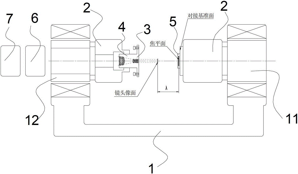
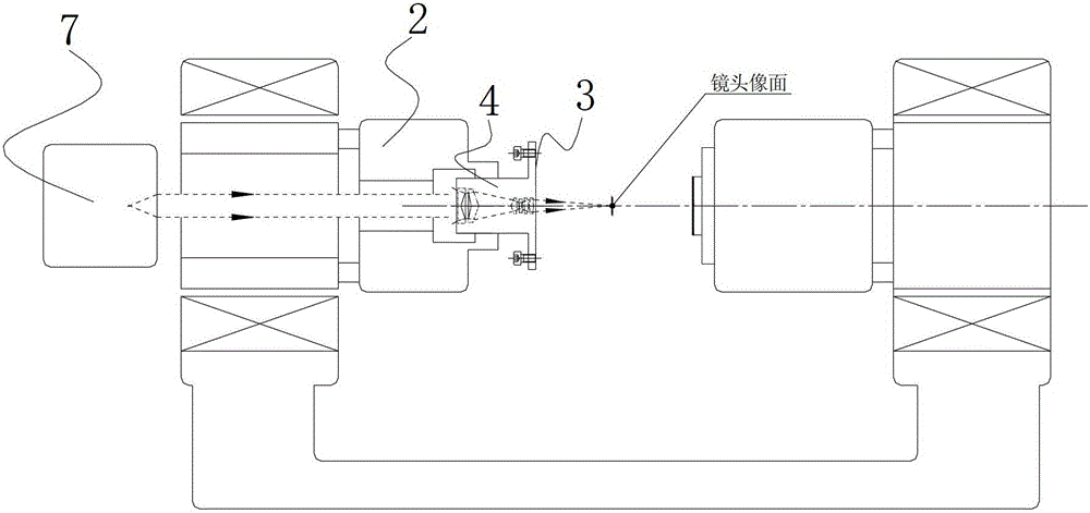
[0027] The invention system consists of borrowing a high-precision two-axis horizontal or two-axis vertical lathe as a platform, such as figure 1 As shown, each of its two rotation axes is fixed with an optical centering adjustment device that can realize four-degree-of-freedom adjustment. The optical lens is fixed on the optical centering adjustment device close to the collimator and the inner focusing centering device. Super-direction collimator and internal focusing and centering instrument; the focal plane component is fixed on another optical centering adjustment device, and its focal plane super-directs to the direction of collimator and internal focusing and centering instrument.

[0028] The method of the invention specifically comprises the following steps:

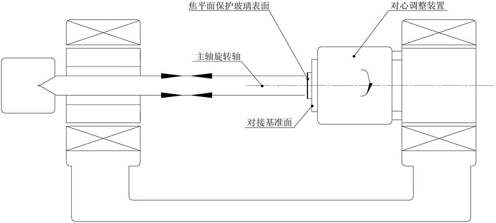
[0029] 1. Adjust the parallelism between the docking reference plane of the focal plane component and the foc...


PUM


Abstract

The invention provides a combined adjusting and jointing method and a combined adjusting and jointing mechanism for a visible light imaging system and an imaging focal plane. The problem that the accuracy of perpendicularity between an optical axis of an optical imaging system and the imaging focal plane, the accuracy of an overlap ratio between the optical axis of the optical imaging system and the central normal of the target surface of the imaging focal plane and the accuracy of an overlap ratio between the image plane of the optical imaging system and the imaging focal plane in the conventional image plane jointing process cannot be ensured is mainly solved. By once clamping of a high-accuracy double-shaft lathe, a set regulation aim is fulfilled, the set regulation accuracy is achieved, and meanwhile, the jointing reference surface of a focal plane component and the end face of an optical lens mounting flange are turned, so that the parallelism between two planes is ensured, and an assembly error, which is caused by a previous assembly link, of the focal plane component and an optical lens is completely eliminated.

Description

technical field [0001] The invention relates to a method and mechanism for realizing high-precision combined adjustment and docking of a visible light imaging system and a focal plane. Background technique [0002] The camera composed of the visible light optical imaging system and the focal plane is an important payload of aircraft in the aviation and aerospace fields, providing video images and high-resolution pictures for various tasks, especially various high-resolution earth observation cameras. This type of long focal length optical The system has very high requirements on the perpendicularity between the optical axis of the optical system and the imaging focal plane, the coincidence degree between the optical axis and the normal line of the target surface of the imaging focal plane, and the coincidence degree between the image plane of the optical system and the imaging focal plane. Ensuring the above-mentioned index requirements has become an important link in determ...

Claims


Application Information

Patent Timeline
Patent Type & Authority Patents(China)
IPC IPC(8): H04N17/00
Inventor 武力曹剑中闫阿奇张兆会张凯胜张志张海峰董森杨洪涛费嘉祺
Owner 西安中科飞图光电科技有限公司
Why Eureka
Try Eureka