Boom for construction machine

A technology of construction machinery and jib, applied in the direction of mechanically driven excavators/dredgers, etc., can solve problems such as large time and labor

Inactive Publication Date: 2013-11-20
NIHON KENKI CO LTD
View PDF5 Cites 13 Cited by
  • Summary
  • Abstract
  • Description
  • Claims
  • Application Information

AI Technical Summary

Problems solved by technology

[0004] Therefore, the boom, which is a working arm for construction machinery, takes a lot of time and labor in the manufacturing process including welding work, and improving workability at the time of assembly has become a big problem.

Method used


Image

  • Boom for construction machine
  • Boom for construction machine
  • Boom for construction machine

Examples


Embodiment Construction

[0032] Hereinafter, the construction machine boom according to the embodiment of the present invention will be described in detail with reference to the drawings, taking the case of being applied to a boom of a hydraulic excavator as an example.

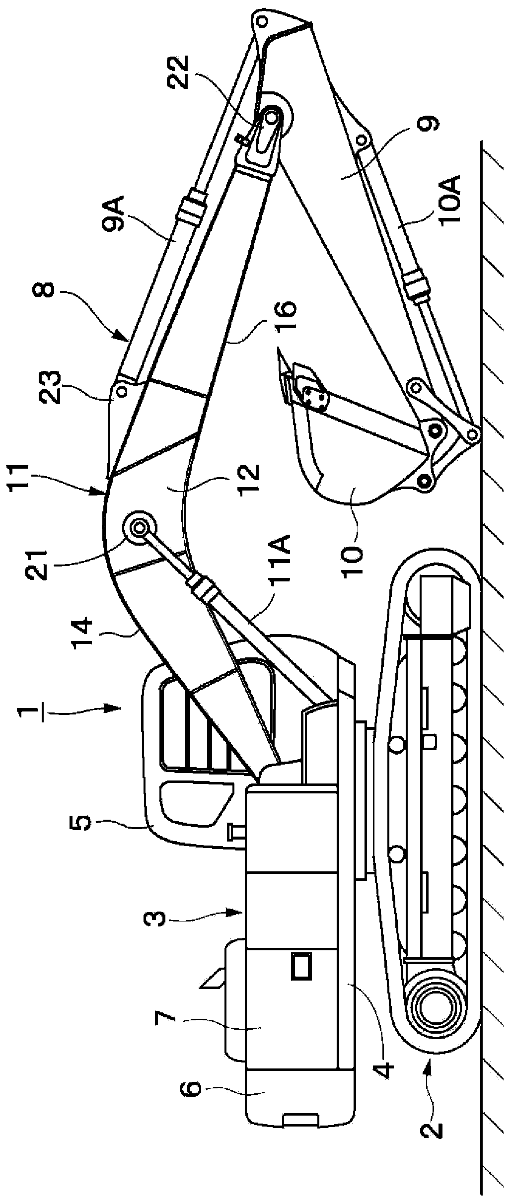
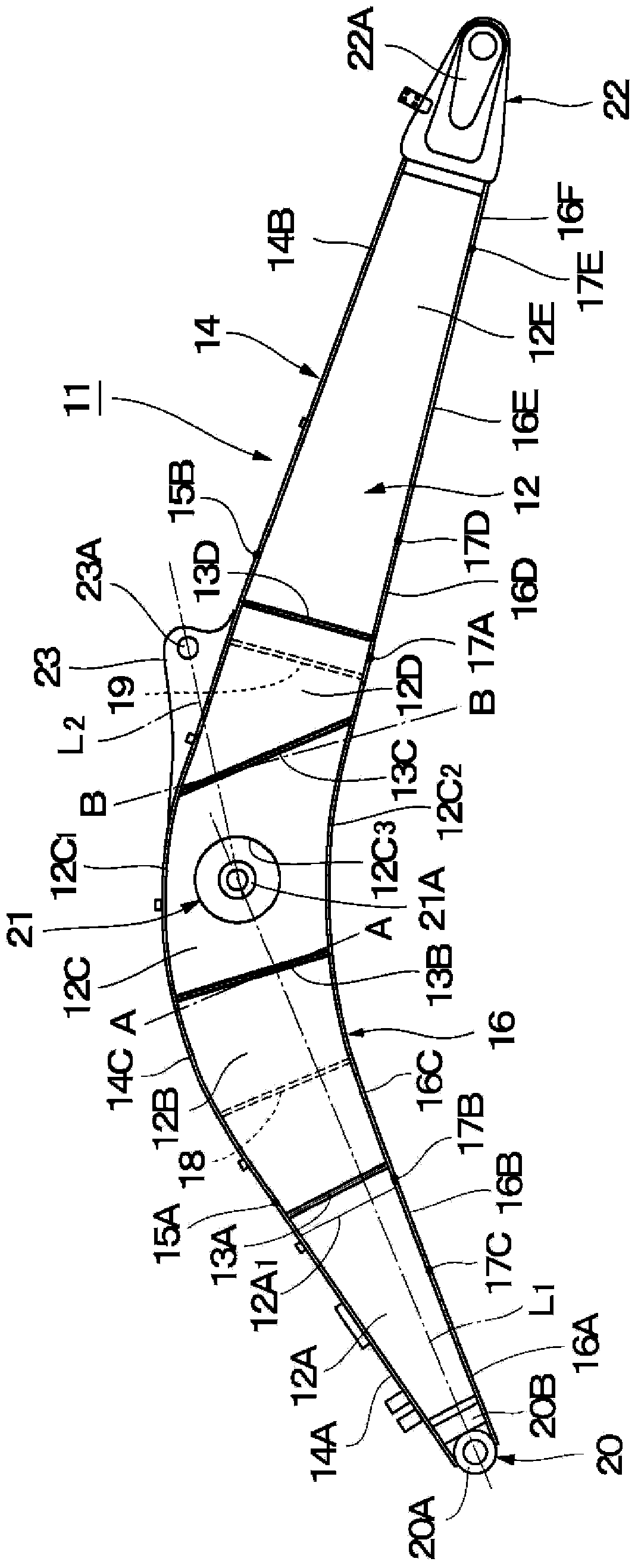
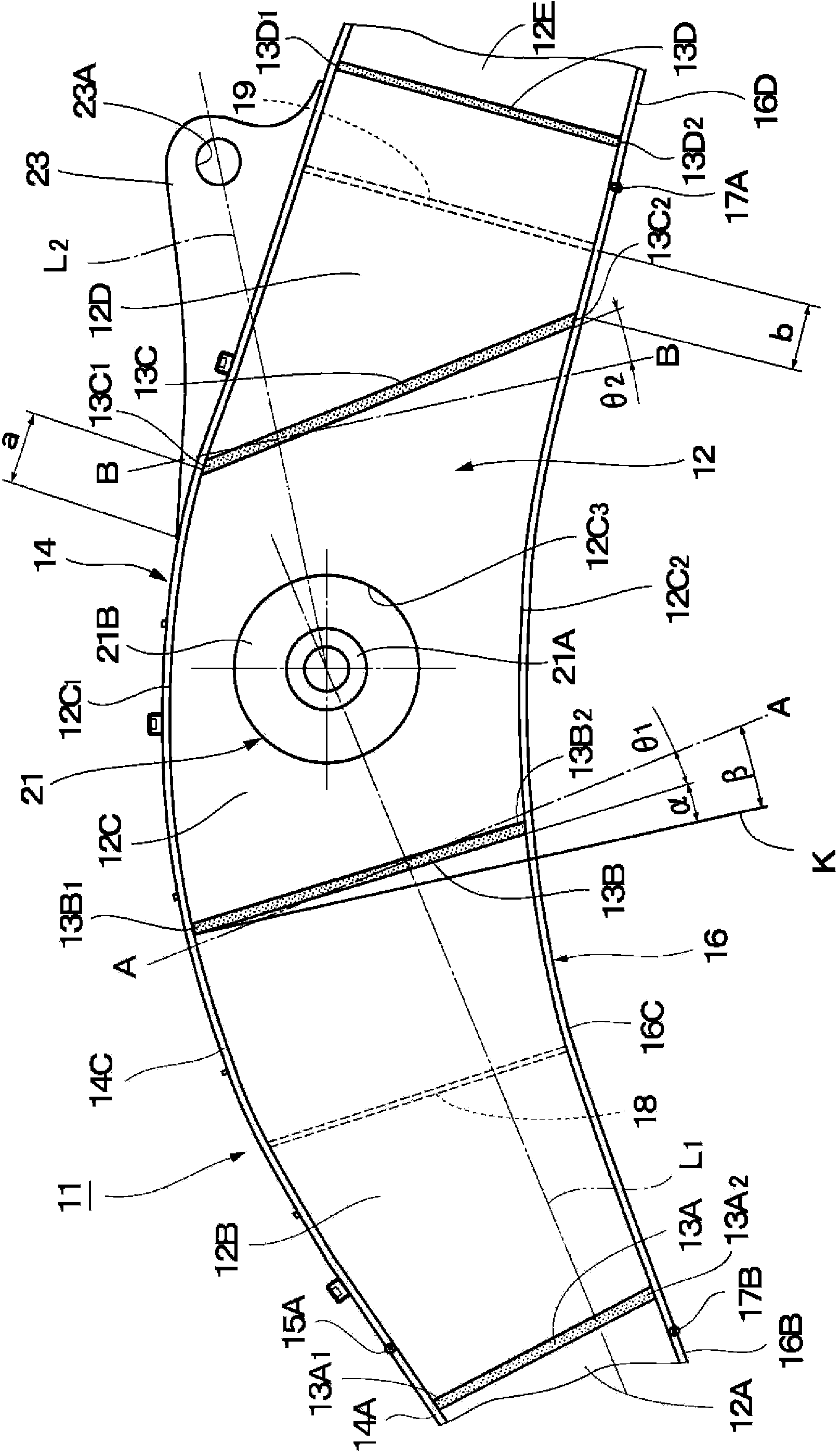
[0033] here, Figure 1 to Figure 9 A boom of a hydraulic excavator according to a first embodiment of the present invention is shown.

[0034] In the figure, symbol 1 is a hydraulic excavator as an engineering machine, and the hydraulic excavator 1 roughly includes: figure 1 A crawler-type undercarriage 2 capable of propelling itself as shown; an upper revolving unit 3 rotatably mounted on the undercarriage 2 ; and a working device 8 described later. The upper revolving body 3 of the hydraulic excavator 1 together with the undercarriage 2 constitutes a vehicle body of the construction machine. The upper revolving body 3 is composed of a revolving frame 4 , a cab 5 , a counterweight 6 , a cabin cover 7 and the like which will be des...


PUM


Abstract

Left and right web plates (12) of a boom (11) are each formed by joining first to fifth web materials (12A-12E) at the ends thereof in the front-back direction along weld lines (13A-13D). An upper flange plate (14) is formed by joining a back upper flange material (14A), a front upper flange material (14B), and an intermediate upper flange material (14C) at the ends thereof in the front-back direction along weld lines (15A, 15B). A lower flange plate (16) is formed by joining first to sixth lower flange materials (16A-16F) at the ends thereof in the front-back direction along weld lines (17A-17E). The weld lines (13A-13D) of the left and right web plates (12), and the weld lines (15A, 15B) of the upper flange plate (14) and the weld lines (17A-17E) of the lower flange plate (16) are disposed at different positions from each other in the front-back direction. Consequently, weight reduction can be achieved by reducing the overall weight while the bending strength, torsional strength, and the like of the boom (11) are ensured.

Description

technical field [0001] The present invention relates to a boom for a construction machine that is suitably used as a working device of a hydraulic excavator as a working arm, for example. Background technique [0002] Generally, a work device installed on a construction machine such as a hydraulic excavator includes: a boom whose base end side is connected to a frame on the vehicle body side in a pitch-movable manner; The boom at the front end side of the boom; working tools such as excavation buckets rotatably connected to the front end side of the boom; and boom cylinders, boom cylinders, working tool cylinder. [0003] The above-mentioned boom in this working device is formed as a box-shaped structure with a quadrangular closed-section structure in cross section. The box-shaped structure includes: left and right webs; the upper flange plate on the upper end side; and the lower flange plate joined to the lower end sides of the above-mentioned left and right webs by weldi...

Claims


Application Information

Patent Timeline
Patent Type & Authority Applications(China)
IPC IPC(8): E02F3/38
CPCE02F3/38
Inventor 高桥毅滨田厚史下平贵之山本光菅谷诚
Owner NIHON KENKI CO LTD
Why Eureka
Try Eureka