
Installation construction method for bridge rigid hinge

An installation method and rigid hinge technology, which can be used in bridges, bridge construction, erection/assembly of bridges, etc., and can solve problems such as inability to adapt, and the impact of cable towers and foundations is greatly affected.

Inactive Publication Date: 2015-06-24
CCCC HIGHWAY CONSULTANTS
View PDF3 Cites 0 Cited by
  • Summary
  • Abstract
  • Description
  • Claims
  • Application Information

AI Technical Summary

Problems solved by technology

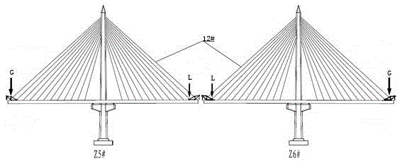
[0010] Due to the long length of the steel box girder, the temperature change of the main girder has a great influence on the force of the cable tower and the foundation. The traditional structure cannot adapt to this long main girder structure system and the special construction environment of the Jiashao Bridge. To solve the problem of beam temperature change, Jiashao Bridge adopts an innovative structural system with two main girders and a rigid hinge device at the middle of the bridge span

Method used


Image

  • Installation construction method for bridge rigid hinge
  • Installation construction method for bridge rigid hinge
  • Installation construction method for bridge rigid hinge

Examples


Embodiment Construction

[0051] All features disclosed in this specification, or steps in all methods or processes disclosed, may be combined in any manner, except for mutually exclusive features and / or steps.

[0052] Any feature disclosed in this specification (including any appended claims, abstract and drawings), unless expressly stated otherwise, may be replaced by alternative features which are equivalent or serve a similar purpose. That is, unless expressly stated otherwise, each feature is one example only of a series of equivalent or similar features.

[0053] The bridge in the present invention adopts a cable-stayed structure with six framing towers. It mainly has two main girders, wherein the two main girders are disconnected at the middle span of the whole bridge to form expansion joints, so that the main girders are divided into two joints. Both are three-tower cable-stayed bridges, and rigid hinges are set in the expansion joints to connect the two girders. The main girder is divided in...


PUM


Abstract

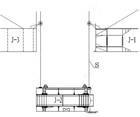
The invention discloses an installation method for a bridge rigid hinge and belongs to the technical field of bridge construction. The installation construction method for the bridge rigid hinge includes the steps that firstly, combination and assembling are performed in advance, a running-in test is performed, and accessories are installed; secondly, preparation is performed before hoisting; thirdly, a small box girder is temporarily locked into a J2 kind end beam; fourthly, synchronous hoisting is in place, entering a preset closure gap position is achieved, and adjustment is performed properly; fifthly, a temporary locking device is installed, temporary locking is relieved, the small box girder is moved close to a J1 beam segment fixing end, and a bolt is used for connection; sixthly, a closure seam of a J2 beam segment and a J3 beam segment is forcefully adjusted, temporary fixing accessories are temporarily fixedly combined and installed, construction site connection of the J2 beam segment and the J3 beam segment is finished, and a beam is installed on the J2 beam segment; seventhly, remained facilities are installed, temporary facilities are detached, and rigid hinge supports on the periphery of the small box girder are adjusted. According to the installation method for the bridge rigid hinge, the rigid hinge and parts of the rigid hinge can be accurately and inerrably installed, the rigid hinge and a bridge are stable in structure, and safety and reliability in using the rigid hinge and the bridge are ensured.

Description

technical field [0001] The invention relates to bridge installation technology, in particular to a rigid hinge installation technology used on bridges. Background technique [0002] In my country, the continuous length of the main girder of the bridge is more than 2680m, and it is a cable-stayed bridge with more than six pylons. One of the main difficulties in its structural system is that the overall stiffness of the multi-tower cable-stayed bridge is small. In order to solve the above problems, the main beam adopts a structural system in which vertical supports are set at a distance of 46m on both sides of the cable tower to improve structural rigidity, and X brackets are installed at each cable tower. The second difficulty of the structural system is that the total length of the main girder reaches more than 2680m, and the temperature deformation of the main girder has a great influence on the stress of the cable tower and the foundation. The height of the tower and the ...

Claims


Application Information

Patent Timeline
Patent Type & Authority Patents(China)
IPC IPC(8): E01D21/00
Inventor 张喜刚王仁贵林道锦孟凡超吴伟胜王梓夫袁洪林昱
Owner CCCC HIGHWAY CONSULTANTS
Learn More