

Multistage step drop energy dissipater structure
A kind of energy dissipator and ladder-type technology, which is applied in water conservancy projects, sea area engineering, coastline protection, etc., can solve the limitations of conventional underflow energy dissipation, increase the energy dissipation effect of auxiliary energy dissipators, and not very ideal drainage buildings to ensure safe operation and service life, avoid vertical shaft vortex damage, and reduce hydraulic indicators
Active Publication Date: 2013-11-27
CHINA THREE GORGES CORPORATION
View PDF9 Cites 10 Cited by
- Summary
- Abstract
- Description
- Claims
- Application Information
AI Technical Summary
Problems solved by technology
However, although these energy dissipation structures can reduce the hydraulic index to a certain extent, a large number of specific studies have shown that there are backflows and vertical axis vortices of different intensities after the water flows into the pool using the expansion and drop energy dissipation structure [Huang Haiyan, Zhang Qiang, Wang Haijun. Expansion Experimental research on the hydraulic characteristics of falling bottom flow energy dissipators. China Rural Water Conservancy and Hydropower. 2010 No. 7: 86-87], resulting in brushing, entrainment and high dynamic water pressure upturning resulting in serious damage to buildings
It can be seen that the application of conventional underflow energy dissipation has relatively large limitations; the energy dissipation effect produced by existing technical measures such as adding auxiliary energy dissipation workers is not very ideal or poses a threat to drainage structures
Method used
View moreImage
Smart ImageViewing Examples

Examples
Embodiment 1
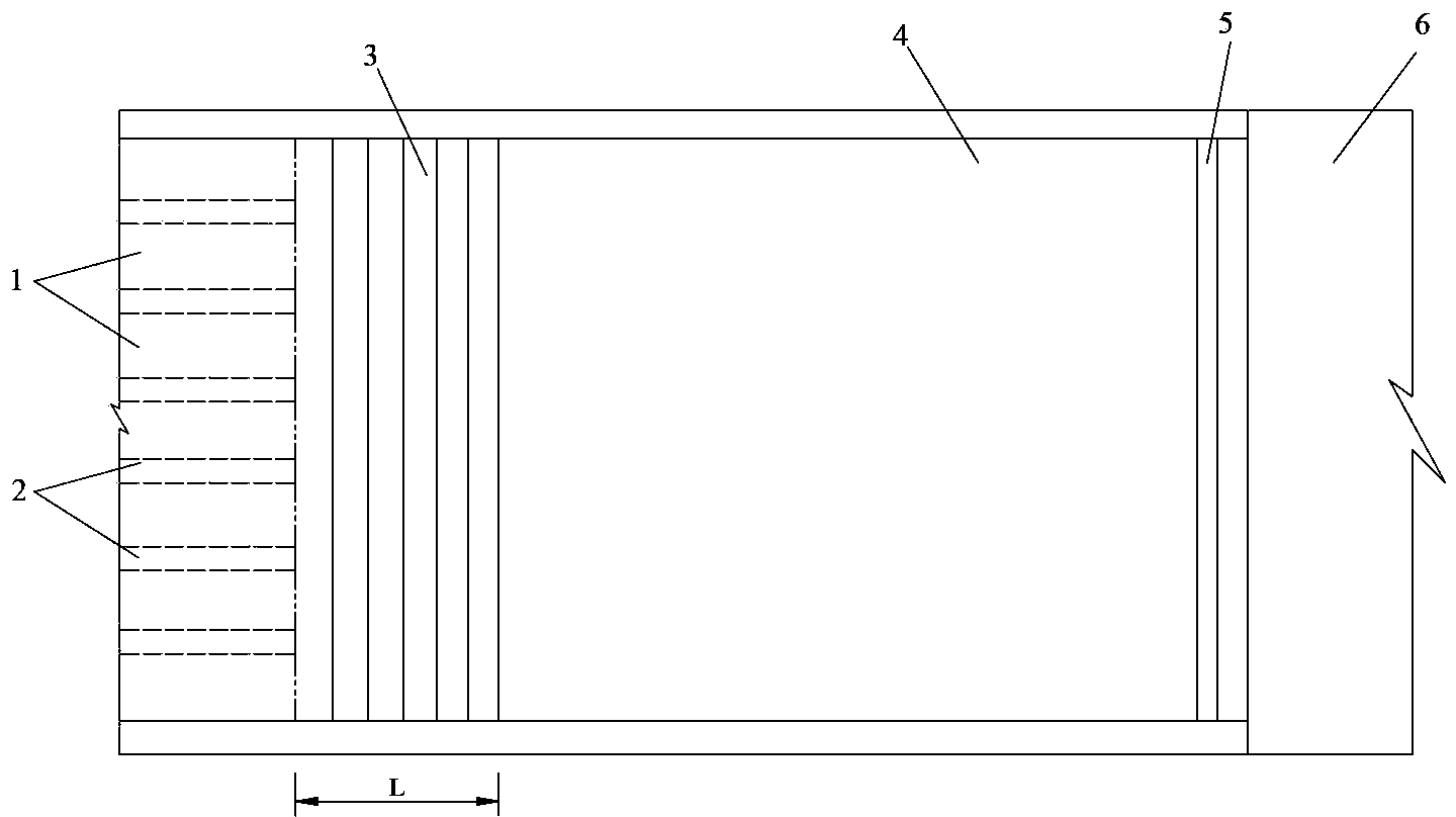
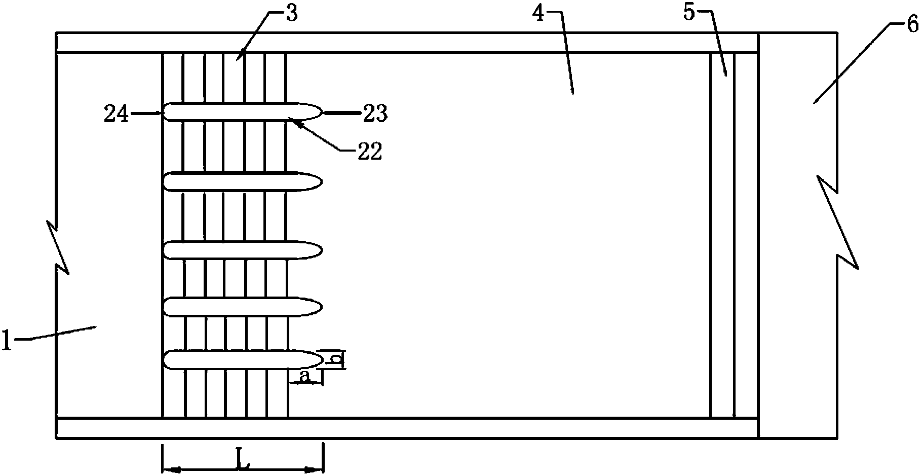
[0055] Embodiment 1 represents the case where the discharge tank 1 is a multi-stream downflow mode, that is, a multi-stream outflow mode, and the multi-level stepped sill structure 3 adopts a continuous type.
Embodiment 2
[0056] Embodiment 2 represents the case where the discharge tank 1 adopts a continuous discharge mode, and the multi-stage stepped sill structure 3 adopts an interval type.
Embodiment 3
[0057] Embodiment 3 represents the case where the discharge tank 1 is a multi-stream downflow mode, that is, a multi-stream outflow mode, and the multi-level stepped sill structure 3 adopts an interval type.
Login to View More PUM
| Property | Measurement | Unit |
|---|---|---|
| Thickness | aaaaa | aaaaa |
Abstract
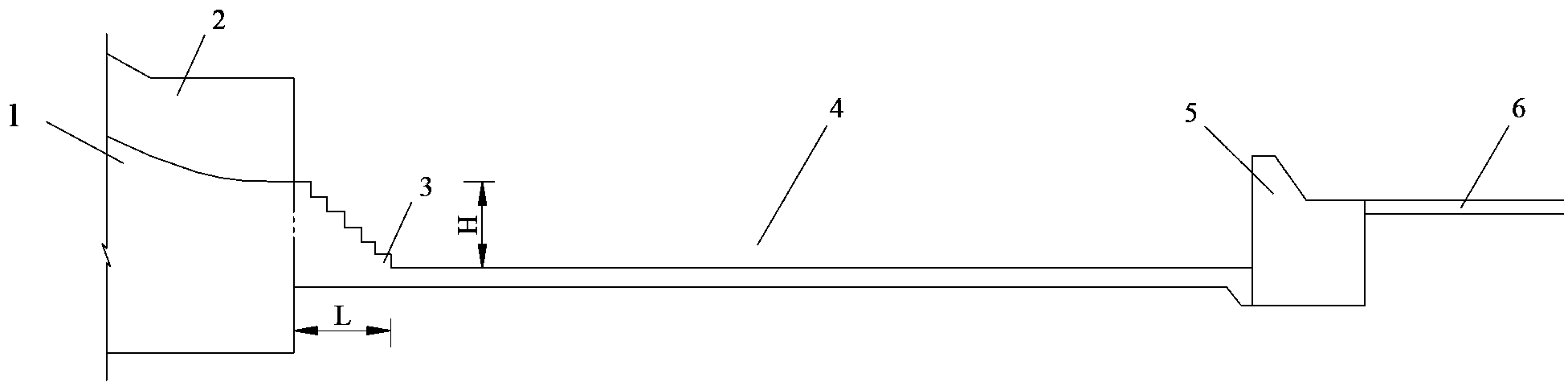
The invention relates to a multistage step drop energy dissipater structure which comprises a flow relief channel, a multistage step drop structure, a stilling pool, a stilling pool tail step and a downstream apron. The tail end of the flow relief channel is connected to the top end of the multistage step drop structure. The bottom end of the multistage step drop structure is connected with the stilling pool. Certain height difference exists between the tail end of the flow relief channel and the base plate of the stilling pool. The bottom of the multistage step drop structure is level with the base plate of the stilling pool which is connected with the downstream apron through the stilling pool tail step. By the multistage step drop energy dissipater structure, water flow turbulence is enhanced, energy dissipation effect is increased, hydraulic indexes in the stilling pool can be reduced, water flow pulsation in the stilling pool is reduced, and the novel energy dissipation device is provided for high-water-head high-flow release buildings. In addition the multistage step drop energy dissipater structure is easy to build and well suitable for upstream continuous or multi-strand flow release.
Description
technical field [0001] The invention relates to the field of water conservancy projects for flood discharge and energy dissipation facilities, in particular to a multi-stage ladder-type falling sill combined energy dissipation structure suitable for high water head and large flow in flood control and flood discharge projects. Background technique [0002] Most of the high dam projects in my country are located in the high mountains and canyons in the west. The common characteristics of flood discharge and energy dissipation are "high water head, large flow, large flood discharge power, narrow river valleys, and complex geological conditions". The flood discharge and energy dissipation technology is difficult and has problems. It is usually accompanied by some special water flow phenomena. Therefore, the design of flood discharge and energy dissipation and safe operation have always been hot issues concerned by the field of water conservancy and hydropower engineering in recent...
Claims
Login to View More Application Information
Patent Timeline
 IPC IPC(8): E02B8/06
Inventor戴会超郑铁刚张培培杨文俊牛志攀
OwnerCHINA THREE GORGES CORPORATION