Gas holder piston oil groove separating weir

A gas tank and piston technology, which is applied in the field of gas tank, can solve the problems of the wear of the weir sliding plate and the poor ability to bear the differential pressure of canvas oil in the weir, and achieve the effects of reducing friction and wear, avoiding the problem of gas leakage and reducing the pressure.

Inactive Publication Date: 2013-11-27
CISDI ENG CO LTD
View PDF8 Cites 0 Cited by
  • Summary
  • Abstract
  • Description
  • Claims
  • Application Information

AI Technical Summary

Problems solved by technology

[0005] In view of this, the purpose of the present invention is to provide a gas tank piston oil ditch separation weir to solve the problem that the existing gas tank piston oil ditch separation weir is not strong enough to bear the oil differential pressure on both sides of the weir canvas, and to solve Severe wear of the slide plate at the weir part of the existing gas tank piston oil ditch separation weir

Method used


Image

  • Gas holder piston oil groove separating weir
  • Gas holder piston oil groove separating weir

Examples


Embodiment Construction

[0012] The present invention will be further described below in conjunction with the accompanying drawings and embodiments.

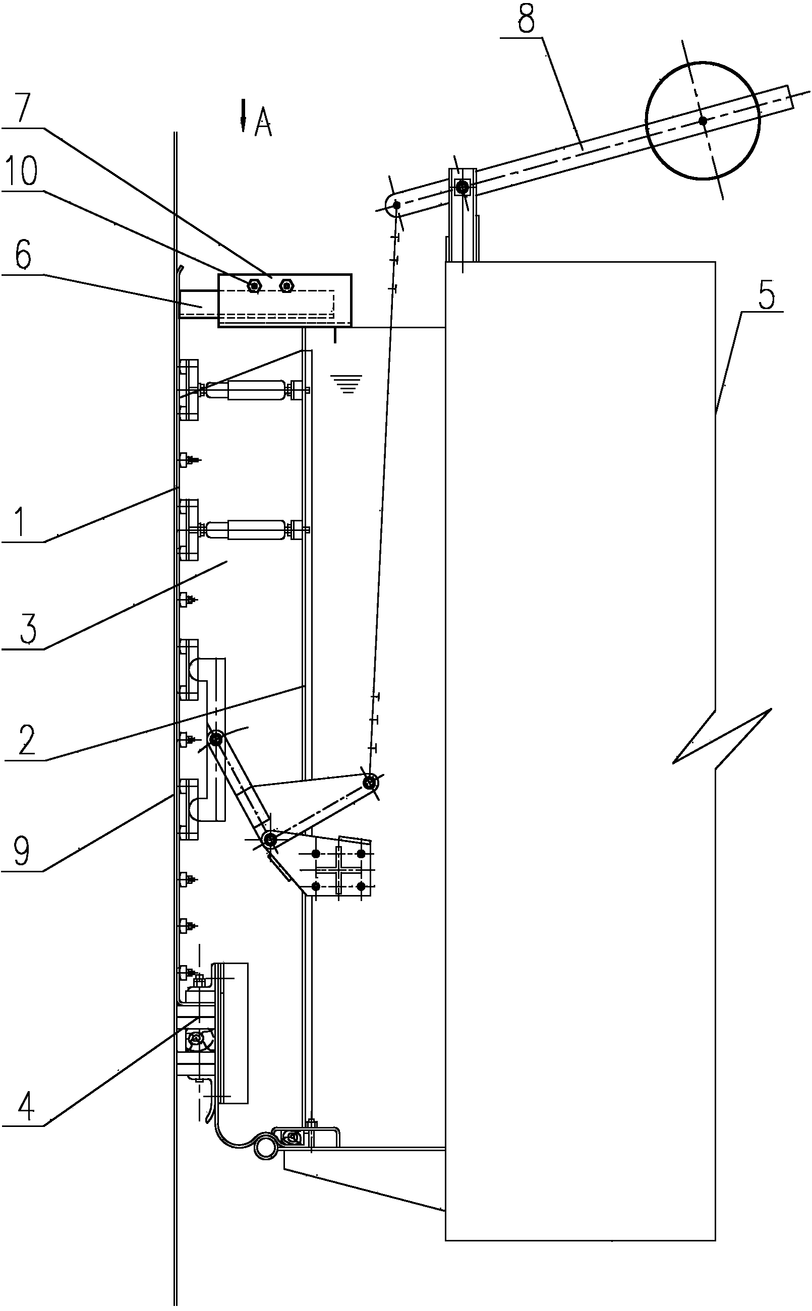
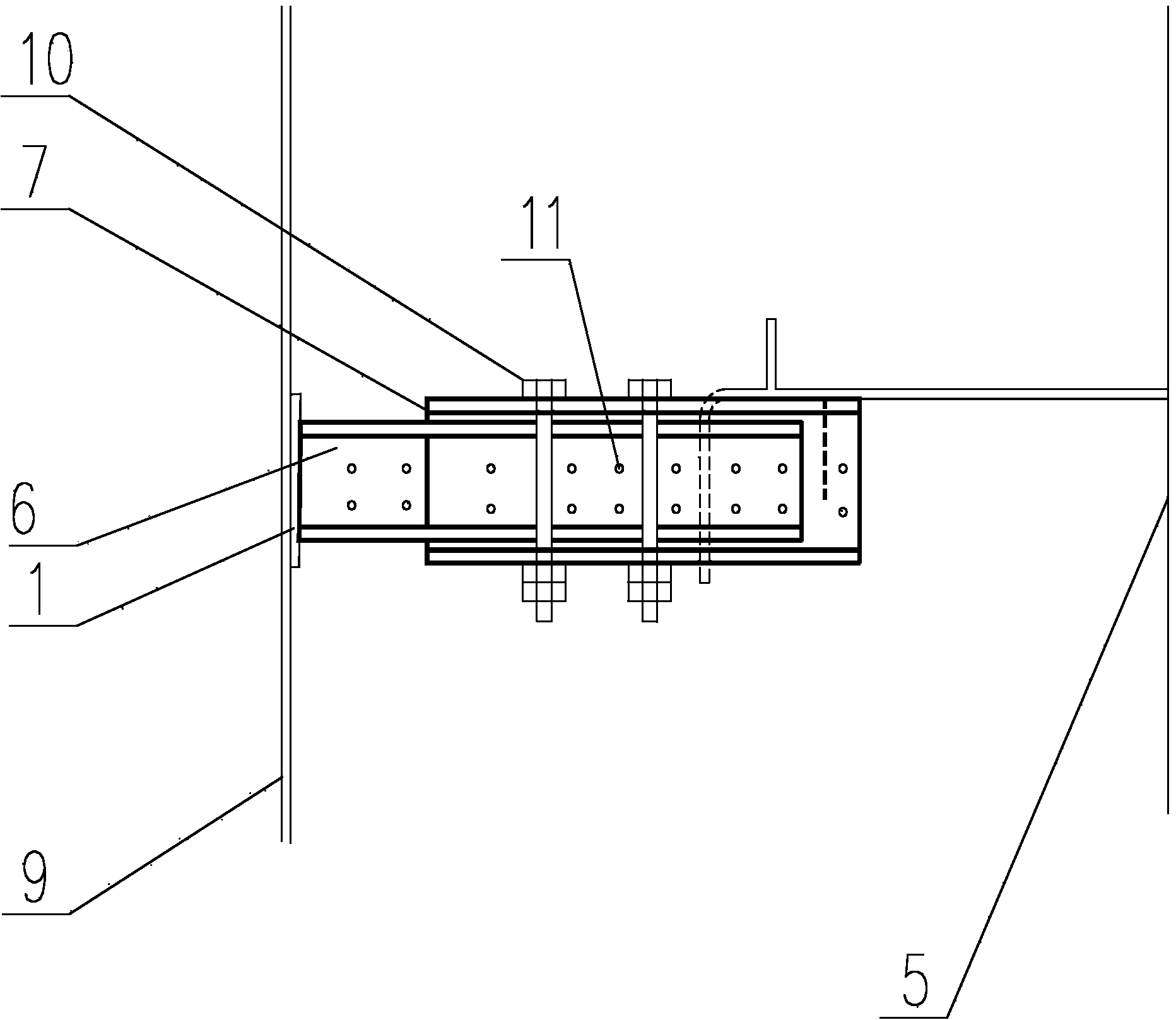
[0013] As shown in the figure, the gas tank piston oil ditch separation weir in this embodiment includes a weir slide plate 1, a weir partition plate 2, a weir canvas 3 and a seal clamping mechanism 4, and the lower end of the weir slide plate 1 is fixed on On the seal clamping mechanism 4, the upper end of the weir slide plate 1 is higher than the upper end of the weir partition plate 2, and the weir slide plate 1 is fixedly connected with a piston 5 at its position higher than the weir partition plate 2. The radially arranged support rods 6 are provided with a guide block 7 with a limit slot on the upper end of the weir partition 2, and the support rod 6 is inserted into the limit slot and slidably fits with the limit slot.

[0014] In this embodiment, the gas tank piston oil ditch separates the weir, which provides a supporting point for the upper en...


PUM


Abstract

The invention discloses a gas holder piston oil groove separating weir, which comprises a weir part slide plate, a weir part separating plate and a sealing element clamping mechanism, wherein the lower end of the weir part slide plate is fixedly arranged on the sealing element clamping mechanism, the upper end of the weir part slide plate is higher than the upper end of the weir part separating plate, a supporting rod arranged along the radial direction of a piston is fixedly connected onto the position, higher than the weir part separating plate, of the weir part slide plate, a guide block with a position limiting groove is arranged on the upper end of the weir part separating plate, and the supporting rod is inserted into the position limiting groove and is in slide matching with the position limiting groove. The gas holder piston oil groove separating weir has the advantages that a supporting point is provided for the upper end of the weir part slide plate through the heightening of the weir part slide plate and the arrangement of the supporting rod and the guide block, so the capability of the weir part slide plate for bearing the oil level difference pressure at two sides of weir part canvas is enhanced, the capability of resisting the pressure in the radial direction of the piston is also enhanced, further, the problems of piston inclination standard exceeding and gas leakage can be effectively avoided, in addition, the pressure of a balance weight lever pressing mechanism on the weir part slide plate can be reduced, and the friction abrasion of the weir part slide plate is reduced.

Description

technical field [0001] The invention relates to a gas cabinet, in particular to an oil ditch separation weir of the gas cabinet. Background technique [0002] The piston oil groove of the thin oil-sealed gas holder sealing device currently used is equipped with a piston oil groove separation system. The piston oil groove separation system is composed of a plurality of sets of sealing oil separation weirs that are basically symmetrically distributed to prevent The one-sided phenomenon of sealing oil can avoid the piston tilting beyond the standard and even gas leakage. With the development of thin oil-sealed gas tanks to high pressure, the sealing oil stored in the piston oil ditch is getting higher and higher, and the oil level difference pressure of the piston oil ditch separation weir is also increasing. The safety of the piston oil ditch separation weir is also increasing. Stable long-term operation has become a frontier research topic in the industry. [0003] Patent N...

Claims


Application Information

Patent Timeline
Patent Type & Authority Applications(China)
IPC IPC(8): F17B1/04
Inventor 高海平袁靖陈乐
Owner CISDI ENG CO LTD
Why Eureka
Try Eureka