Method for measuring spot intensity distribution of reflective concentrating photovoltaic concentrator

A concentrating photovoltaic and intensity distribution technology, which is applied in the direction of testing optical properties, can solve problems such as high energy flow density, and achieve the effect of simple operation and easy operation

Active Publication Date: 2018-06-26
兰州大成科技股份有限公司 +1
View PDF7 Cites 0 Cited by
  • Summary
  • Abstract
  • Description
  • Claims
  • Application Information

AI Technical Summary

Problems solved by technology

[0008] Because the high-power reflective concentrator concentrates light energy on the target surface and has a large flux density, the existing detectors cannot be directly used for direct measurement

Method used


Image

  • Method for measuring spot intensity distribution of reflective concentrating photovoltaic concentrator
  • Method for measuring spot intensity distribution of reflective concentrating photovoltaic concentrator
  • Method for measuring spot intensity distribution of reflective concentrating photovoltaic concentrator

Examples


Embodiment

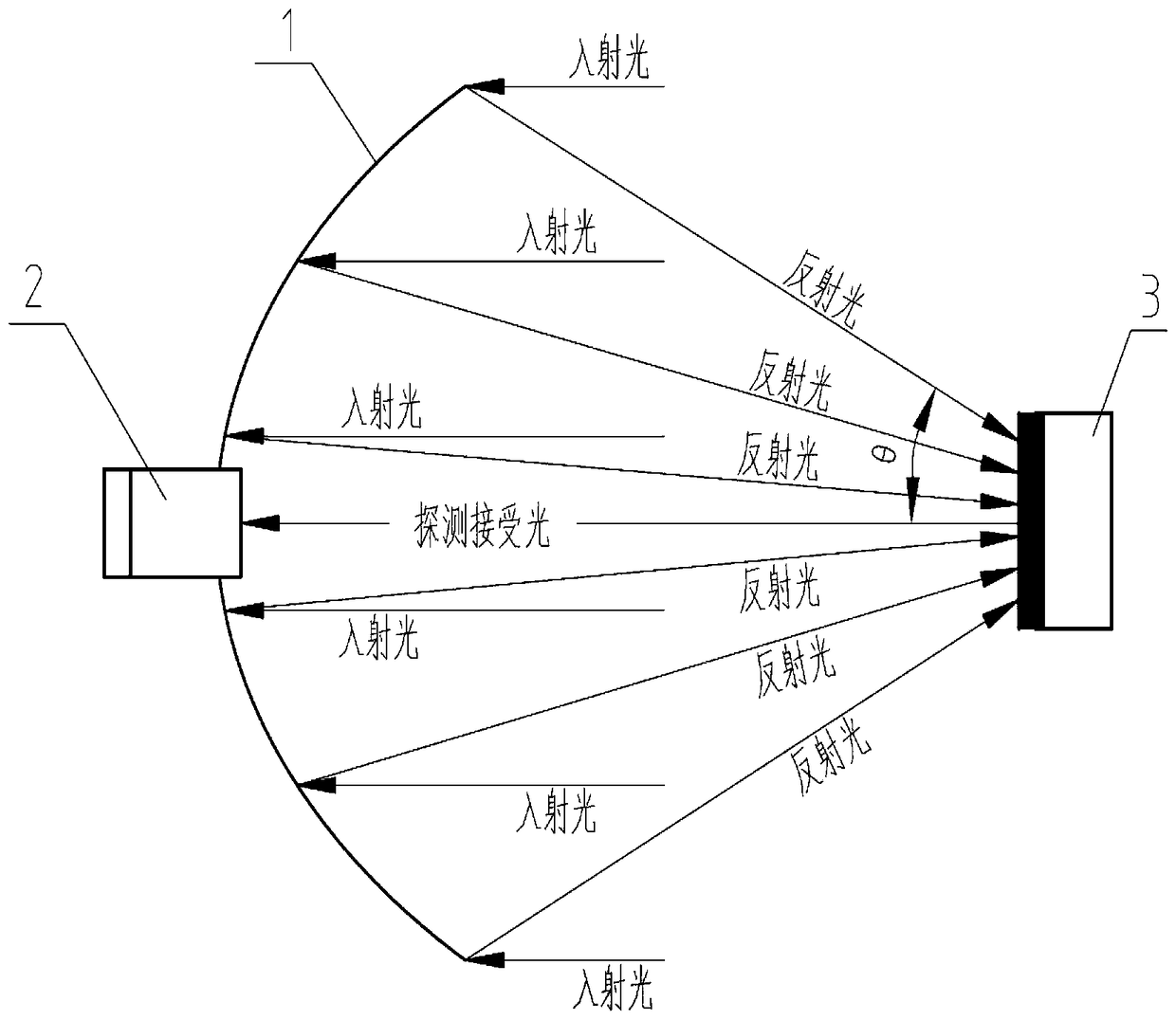
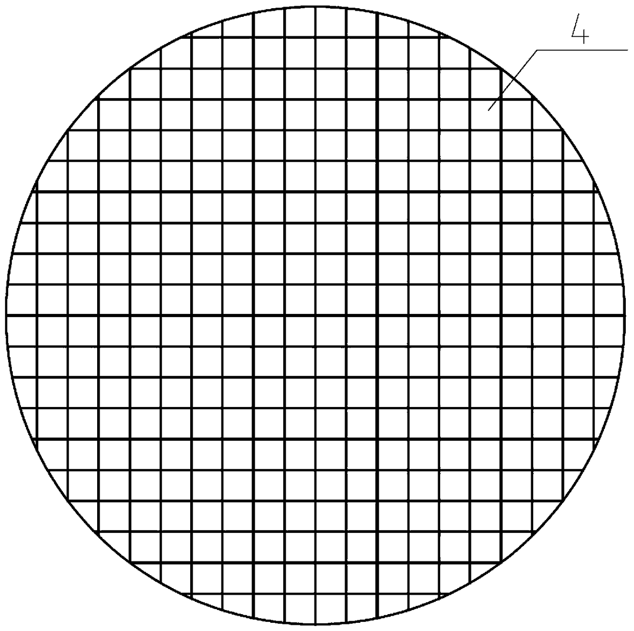
[0028] Example: see figure 1 , a method for measuring the spot intensity distribution of a reflective concentrating photovoltaic concentrator is characterized in that it comprises the following steps: (1) dividing a rotating parabolic reflector into reflectors of a certain area; (2) using a detector to record the passage of sunlight The imaging of each reflection element on the reflection plate after reflection is a pixel; (3) superimpose each pixel to obtain the light intensity distribution on the reflection plate of the reflective concentrator.

[0029] The area of ​​the reflective element needs to be smaller than the area of ​​the reflective plate.

[0030] When recording sunlight on the picture elements on the reflector after being reflected by each reflector, the detector is fixed at the lowest point of the rotating parabolic reflector. The detector is fixed at the apex of the rotating paraboloid, that is, the lowest point, which is always at the same position during the...

experiment example

[0039] Experimental example: see figure 1 , a method for measuring spot intensity distribution of reflective concentrating photovoltaic concentrators,

[0040] The opening section of the rotating parabolic reflector 1 concentrator is a circle with a diameter of 3.2 m.

[0041] Detector 2 is a commercially available digital camera. Installed at the lowest point of the parabolic reflector of revolution, that is, at the vertex of the parabola with the largest profile.

[0042] The reflector 3 is an ordinary plane reflector with a mirror size of 200mm×200mm and a mirror reflectivity of 93%.

[0043] The reflector 3 is 2.77m away from the opening section of the rotating parabolic reflector 1 .

[0044] The measurement of the light intensity distribution on the reflector 3 after sunlight is reflected by the rotating parabolic reflector 1 is carried out according to the following steps:

[0045] (1) dividing the rotating parabolic reflecting surface 1 into reflecting elements 4 o...


PUM


Abstract

The invention relates to reflecting type concentrating photovoltaics, in particular to a method for measuring the distribution of the intensity of light spots of a reflecting type concentrating photovoltaic condenser. The method for measuring the distribution of the intensity of the light spots of the reflecting type concentrating photovoltaic condenser is characterized by including the following steps that a rotating parabolic reflecting surface is divided into reflecting elements with a certain area; a detector is utilized to record imaging of sunlight on a reflecting plate after the sunlight is reflected by the reflecting elements, and the imaging is used as image elements; the image elements are stacked to obtain the distribution of the light intensity on the reflecting plate of the reflecting type condenser. The method has the advantages that a method which is simple and convenient to operate and used for measuring the uniformity of the light spots is provided for the high-power reflecting type concentrating photovoltaics, so that it is possible to measure the uniformity of the light spots which are high in energy current density and to measure the spacial distribution of the light intensity of the light spots which are high in energy current intensity.

Description

technical field [0001] The invention relates to reflective concentrating photovoltaics, in particular to a method for measuring spot intensity distribution of reflective concentrating photovoltaic concentrators. Background technique [0002] The concentrating photovoltaic system is composed of a heliostat, a concentrating cell module, a concentrator and related power and heat dissipation devices. It adopts a focusing method to greatly increase the light energy density of sunlight (more than 400 times), so that the conversion efficiency of solar cells is improved. , to obtain a large current on a small area battery chip. Fresnel lens or parabolic reflector can be used to focus the sunlight, and the heat dissipation of solar concentrator cells is naturally cooled by large-area heat sinks, or the heat is reused by cooling with circulating water. [0003] There are mainly two types of high-power concentration methods used in concentrated photovoltaic systems: reflection and tra...

Claims


Application Information

Patent Timeline
Patent Type & Authority Patents(China)
IPC IPC(8): G01M11/02
Inventor 范多旺王成龙范多进
Owner 兰州大成科技股份有限公司
Why Eureka
Try Eureka