A First Aid Method for Hall Position Sensor Failure

A technology of sensor failure and Hall position, which is applied to electrical components, motor control, control systems, etc., can solve problems such as rough processing methods and system paralysis, and achieve the effects of optimizing costs, reducing hazard levels, and increasing reliability

Active Publication Date: 2015-12-02
NORTHWESTERN POLYTECHNICAL UNIV
View PDF3 Cites 2 Cited by
  • Summary
  • Abstract
  • Description
  • Claims
  • Application Information

AI Technical Summary

Problems solved by technology

This processing method is too rough. If the motor is the key component at this time, this processing method will immediately paralyze the system, which may cause disastrous consequences.

Method used


Image

  • A First Aid Method for Hall Position Sensor Failure
  • A First Aid Method for Hall Position Sensor Failure
  • A First Aid Method for Hall Position Sensor Failure

Examples


Embodiment Construction

[0030] This embodiment is a first aid method for Hall position sensor failure.

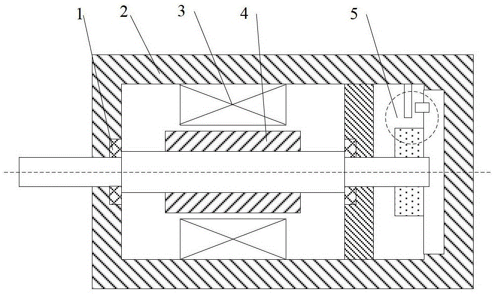
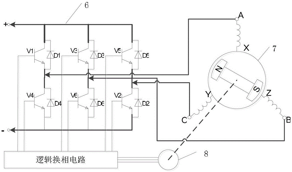
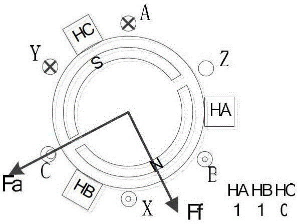
[0031] figure 1 It is a structural schematic diagram of a brushless DC motor. It can be seen from the figure that the position sensor is located inside the motor body, which is easily affected by strong magnetic fields and vibrations, and is prone to failure. The control system of the brushless DC motor adopts a three-phase full-bridge structure; figure 2 As shown, T1-T6 are power switch tubes, and D1-D6 are freewheeling diodes. Using this topology, different magnetic potentials can be generated through different switch combinations to drive the motor to rotate. The commutation process of the brushless DC motor and the corresponding Hall switch state are shown in Figures 3a to 3f. The specific Hall switch status as Figure 4 shown. In this embodiment, TMS320F2812 is used as the main control chip, IR2130 is used as the driving chip, and a three-phase bridge inverter circuit and a chopping meth...


PUM


Abstract

The invention discloses a Hall position sensor fault emergency method. After a Hall position sensor fails, a motor is not directly closed, the motor can continue working on the basis of giving an alarm, the hazard rating of the failure of the Hall position sensor is greatly reduced, and the reliability of a system is increased. The Hall position sensor fault emergency method comprises the steps that during the process when the motor runs, three routes of Hall position sensors can have eight kinds of status at most, wherein the all-zero or all-one status is the fault status, and 0 is respectively assigned to initial values; the time when the motor rotates by two ringsis used as a detection period, and if one status of the Hall position sensors appears, 1 is assigned to a corresponding variable; the value of an array is observed; when the motor fails, which one of the Hall position sensors fails is analyzed and determined by analyzing the 0 status; the failure of the one Hall position sensor is accurately positioned through software, and a user can timely and accurately replace the fault sensor according to the fault information after the system stops working.

Description

technical field [0001] The invention relates to a fault handling method of a brushless direct current motor, in particular to a first aid method for a fault of a Hall position sensor. Background technique [0002] In recent years, with the development of power electronics technology, microelectronics technology and new magnetic materials, brushless DC motors are widely used in aviation, aerospace, numerical control because of their small size, light weight, high efficiency, large torque and good speed regulation performance. Machine tools, robots and other fields have been widely used. The basic structure of a brushless DC motor consists of a motor body, a controller, and a position sensor. The function of the position sensor is to detect the position of the main rotor during the movement process, convert the position signal of the magnetic steel pole of the rotor into an electrical signal, and provide the correct commutation information for the logic switch circuit to cont...

Claims


Application Information

Patent Timeline
Patent Type & Authority Patents(China)
IPC IPC(8): H02P29/02
Inventor 相里康马瑞卿韩伟键张震
Owner NORTHWESTERN POLYTECHNICAL UNIV
Why Eureka
Try Eureka