

Method for on-demand routing of mobile self-organizing network based on link quality
A mobile self-organizing, on-demand routing technology, applied in network topology, electrical components, wireless communication, etc., can solve the problems of lack of on-demand routing protocol, difficulty in sensing the optimal link, etc., to achieve tracking maintenance and improve response. effect of speed
- Summary
- Abstract
- Description
- Claims
- Application Information
AI Technical Summary
Problems solved by technology
Method used
Image

Examples
Embodiment
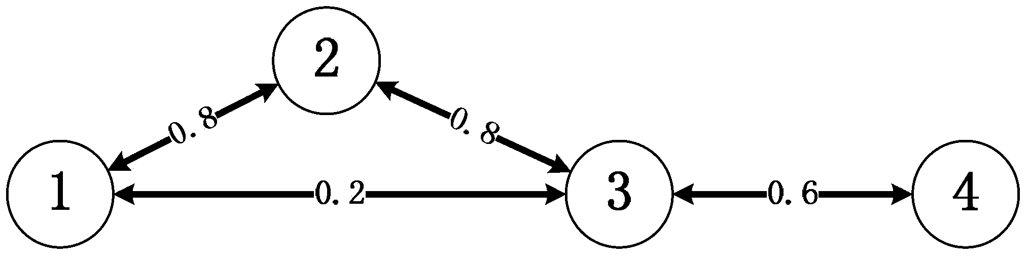
[0035] figure 1 is the topology diagram of the mobile ad hoc network based on the TCP / IP protocol in the embodiment. In this embodiment, the mobile ad hoc network includes 4 nodes, each circle represents a node, where the number represents the node number, each edge represents a direct link, and the value represents the data packet delivery rate. It can be seen that in this embodiment, the adjacent nodes of node 1 are 2, 3, the adjacent nodes of node 2 are 1, 3, the adjacent nodes of node 3 are 1, 2, 4, and the adjacent nodes of node 4 are 3 .
[0036] The following is based on figure 1 The shown mobile ad hoc network describes in detail the on-demand routing method of the present invention based on the link quality of the mobile ad hoc network, and the present invention includes the following steps:
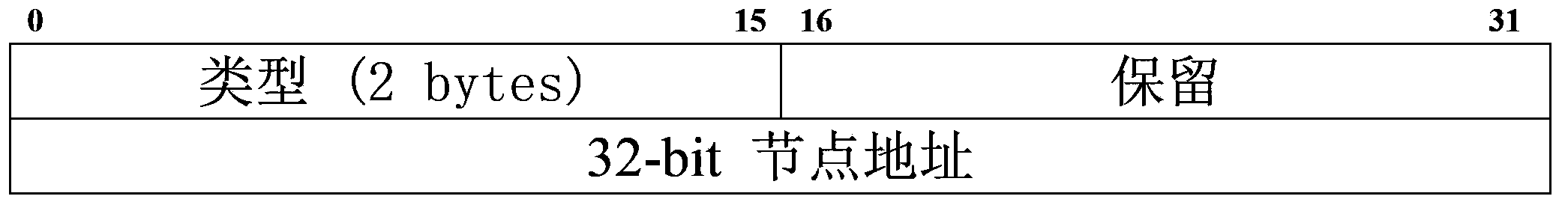
[0037] S1: Every active node i joins the network every T 0 Second broadcast a HELLO message, including the message type and the address of the node, and at the same time lis...
PUM
 Abstract
Description
Claims
Application Information