Square workpiece fixture of milling machine
A workpiece fixture, square technology, applied in the direction of manufacturing tools, metal processing machinery parts, clamping, etc., can solve the problems of low stability of workpiece side processing, long auxiliary time of workpiece processing, high labor intensity, etc., to achieve clamping effect Obvious, easy to control clamping force, simple structure
- Summary
- Abstract
- Description
- Claims
- Application Information
AI Technical Summary
Problems solved by technology
Method used
Image

Examples
Embodiment 1
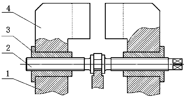
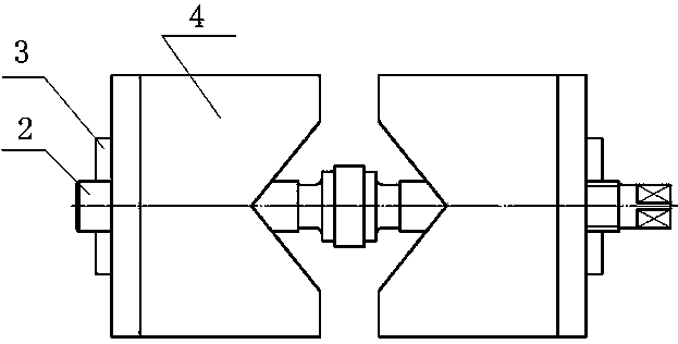
[0017] like figure 1 , figure 2 As shown, the milling machine square workpiece fixture includes a fixture seat, a slide rail 1, an adjusting screw 2, a moving block 3, and a clamping block 4. The lower end of the slide rail 1 is installed on the fixture seat, and the upper end of the slide rail 1 is stuck on the lower end of the moving block 3. On the concave edge, the lower end of the clamping block 4 is pressed on the upper end concave edge of the moving block 3, and the adjusting screw 2 is engaged with the moving block 3.
[0018] The clamping surface of the clamping block 4 is composed of four planes, the planes have the same size, and the angle between two adjacent planes is 90°. The length and width in the plane are 150mm; the clamping block 4 is inlaid with tungsten carbide-based hard alloy on its clamping surface.
Embodiment 2
[0020] like figure 1 , figure 2 As shown, the milling machine square workpiece fixture includes a fixture seat, a slide rail 1, an adjusting screw 2, a moving block 3, and a clamping block 4. The lower end of the slide rail 1 is installed on the fixture seat, and the upper end of the slide rail 1 is stuck on the lower end of the moving block 3. On the concave edge, the lower end of the clamping block 4 is pressed on the upper end concave edge of the moving block 3, and the adjusting screw 2 is engaged with the moving block 3.
[0021] The clamping surface of the clamping block 4 is composed of four planes, the planes have the same size, and the angle between two adjacent planes is 90°. The in-plane length and width of each are 130 mm; the clamping block 4 is inlaid with titanium carbonitride-based cemented carbide on its clamping surface.
Embodiment 3
[0023] like figure 1 , figure 2 As shown, the milling machine square workpiece fixture includes a fixture seat, a slide rail 1, an adjusting screw 2, a moving block 3, and a clamping block 4. The lower end of the slide rail 1 is installed on the fixture seat, and the upper end of the slide rail 1 is stuck on the lower end of the moving block 3. On the concave edge, the lower end of the clamping block 4 is pressed on the upper end concave edge of the moving block 3, and the adjusting screw 2 is engaged with the moving block 3.
[0024] The clamping surface of the clamping block 4 is composed of four planes with the same size. The angle between two adjacent planes on the clamping block 4 is 120°, and its length along the vertical direction of the front view is 210 mm. The length and width of the plane perpendicular to the vertical direction of the front view are both 190 mm; the clamping block 4 is inlaid with titanium carbonitride-based cemented carbide on its clamping surfac...
PUM
 Abstract
Description
Claims
Application Information
 - R&D
- Intellectual Property
- Life Sciences
- Materials
- Tech Scout
- Unparalleled Data Quality
- Higher Quality Content
- 60% Fewer Hallucinations
Browse by: Latest US Patents, China's latest patents, Technical Efficacy Thesaurus, Application Domain, Technology Topic, Popular Technical Reports.
© 2025 PatSnap. All rights reserved.Legal|Privacy policy|Modern Slavery Act Transparency Statement|Sitemap|About US| Contact US: help@patsnap.com