
Device and method for manufacturing optical films

A technology for optical film and manufacturing device, which is applied to flat products, household appliances, other household appliances, etc., can solve the problems of poor light transmittance, long process, low efficiency, etc., to improve the degree of thinning of optical film. , the effect of reducing thickness

Inactive Publication Date: 2013-12-04
HONG FU JIN PRECISION IND (SHENZHEN) CO LTD +1
View PDF0 Cites 1 Cited by
  • Summary
  • Abstract
  • Description
  • Claims
  • Application Information

AI Technical Summary

Problems solved by technology

First, the pattern transfer and curing are carried out separately, the process is long and the efficiency is low; second, the use of PET film as the carrier limits the further thinning of the optical film
Third, the light transmittance of the PET film itself is about 90%, so the optical film will inevitably reduce the light transmission by about 10%, resulting in poor light transmittance; moreover, the optical film is only formed on one side Microstructures that scatter light, but optical films with single-sided microstructures do not guide light well

Method used


Image

  • Device and method for manufacturing optical films
  • Device and method for manufacturing optical films
  • Device and method for manufacturing optical films

Examples


Embodiment Construction

[0013] The manufacturing device and manufacturing method of the optical film of the present invention will be described in detail below with reference to the accompanying drawings.

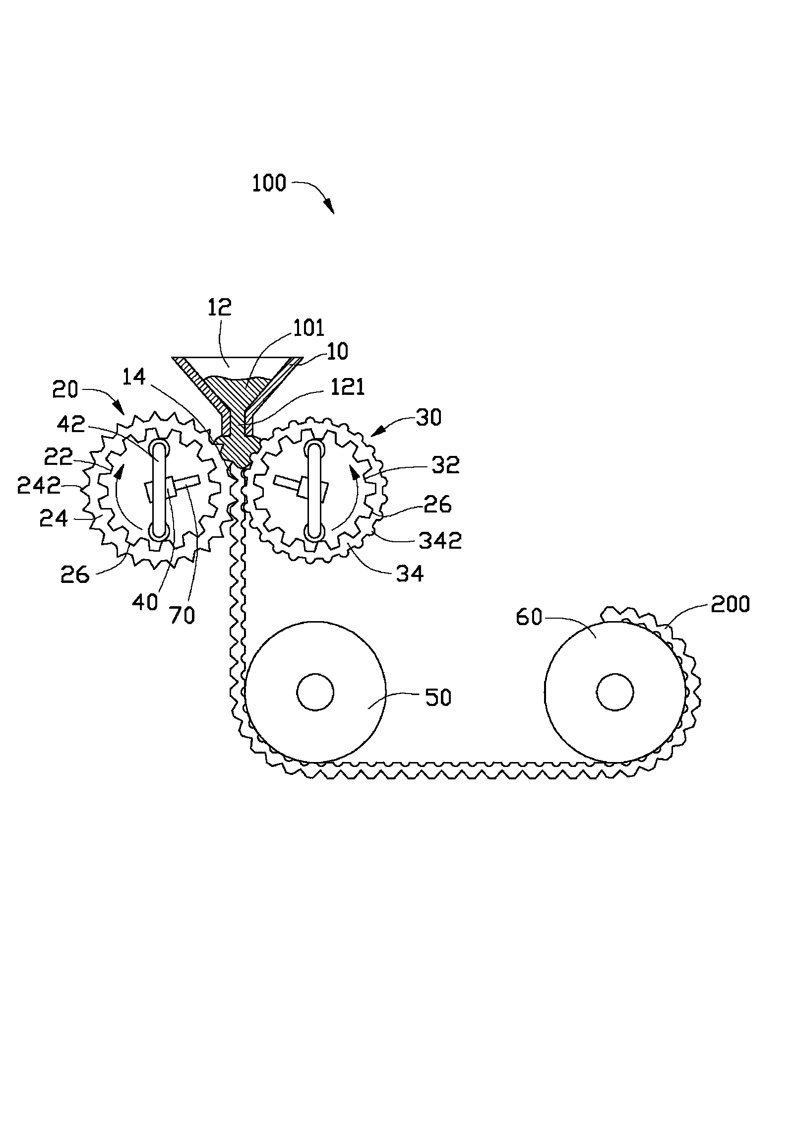
[0014] see figure 1 , shows a manufacturing device 100 of an optical film 200 according to the first embodiment of the present invention, including a feeding part 10 , a first roller 20 , a second roller 30 , and two ultraviolet light sources 40 .

[0015] The supply part 10 is used for supplying the molten ultraviolet curable resin 101 , and the supply part 10 includes a reciprocating coater or a precision coater, and may also include a scraper in other embodiments. The supply part 10 includes a feed port 12 and a corresponding discharge pipe 14, the discharge pipe 14 extends along a predetermined direction, the ultraviolet curable resin 101 enters the feed part 10 from the feed port 12, and flows along the Outlet pipe 14 flows out.

[0016] The first roller 20 is located below the discharge pi...


PUM


Abstract

The invention relates to a device for manufacturing optical films. The device comprises a material feeding part, a first wheel, a second wheel, and at least one UV light source. The material feeding part is provided with a material discharge pipe extending along a predetermined direction. The central axis of the first wheel and the central axis of the second wheel are in the same horizontal surface and are both perpendicular to the predetermined direction. The first wheel and the second wheel are both under the material discharge pipe, and each wheel comprises a gear-type body and a mold insert surrounding the outer side of the gear-type body. The second wheel is arranged at a predetermined distance away from the first wheel to form a molding channel. Together the first wheel and the second wheel are used to press UV curable resin which flows into the molding channel. The at least one ultraviolet light source is placed inside the gear-type body. The invention also relates to a method for manufacturing optical films.

Description

technical field [0001] The invention relates to a manufacturing device of an optical film and a manufacturing method of the optical film. Background technique [0002] At present, in the manufacture of optical films, PET film is generally used as a carrier, and UV (ultraviolet) resin is coated on the surface of PET film first, and microstructure patterns are transferred on the UV resin. After the transfer is completed, the UV resin is irradiated with UV light to cure the UV resin on the surface of the PET film. First, the pattern transfer and curing are carried out separately, the process is long and the efficiency is low; second, the use of PET film as a carrier limits the further thinning of the optical film. Third, the light transmittance of the PET film itself is about 90%, so the optical film will inevitably reduce the light transmission by about 10%, resulting in poor light transmittance; moreover, the optical film is only formed on one side Microstructures that scat...

Claims


Application Information

Patent Timeline
IPC IPC(8): B29C69/00B29C59/04B29C41/24B29C35/10B29L7/00
Inventor 许嘉麟
Owner HONG FU JIN PRECISION IND (SHENZHEN) CO LTD
Learn More