Driving device of platen automatic die cutting hot stamping machine moving platform

A driving device, flat automatic technology, applied in printing presses, rotary printing machines, printing, etc., can solve the problems of toggle mechanism load concentration, high material strength requirements, affecting equipment performance stability and service life, etc., to achieve high The effect of quality bronzing

Inactive Publication Date: 2013-12-04
BEIJING INSTITUTE OF GRAPHIC COMMUNICATION
View PDF6 Cites 1 Cited by
  • Summary
  • Abstract
  • Description
  • Claims
  • Application Information

AI Technical Summary

Problems solved by technology

[0005] Described crankshaft-connecting rod driving mechanism is made up of components such as upper toggle 102, lower toggle 103, connecting rod 105, crankshaft 104, and crankshaft 104 is used as power input shaft, drives connecting rod 105 and upper toggle 102, lower by rotating. The toggle lever 103 moves, so that the movable platform 101 reciprocates up and down. Since the linkage mechanism cannot realize that the movable platform is still at the die-cutting position for a period of time, in practical applications, the platform is positioned at the highest point by lengthening the connecting rod 105. When the crankshaft 104 and the connecting rod 105 are just at the dead point, the pressure maintaining effect is achieved through the large pressure transfer coefficient at the dead point, but this method will cause the load on the toggle mechanism to be too concentrated, and the material strength requirements are high, which will affect the equipment. Performance stability and service life

Method used


Image

  • Driving device of platen automatic die cutting hot stamping machine moving platform
  • Driving device of platen automatic die cutting hot stamping machine moving platform
  • Driving device of platen automatic die cutting hot stamping machine moving platform

Examples


Embodiment Construction

[0025] In order to make the object, technical solution and advantages of the present invention clearer, the present invention will be described in further detail below in conjunction with specific embodiments and with reference to the accompanying drawings.

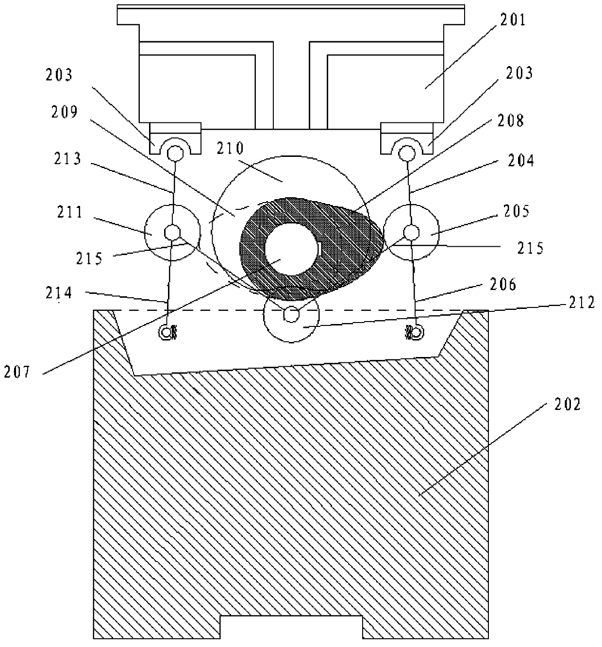
[0026] refer to figure 2 As shown, it is a structural schematic diagram of a flat-pressing automatic die-cutting bronzing motorized platform driving device according to an embodiment of the present invention. The flat-pressing flat automatic die-cutting and bronzing motorized platform driving device is arranged between the moving platform 201 and the base 202, The flat pressing flat automatic die-cutting bronzing motorized platform driving device includes a drive shaft 207, a first cam 208, a second cam 209, a first driven roller 205, a second driven roller 211, a third driven roller 212, a An upper toggle 204 , a second upper toggle 213 , a first lower toggle 206 and a second lower toggle 214 . Wherein, the driving sha...


PUM


Abstract

The invention discloses a driving device of a platen automatic die cutting hot stamping machine moving platform. The driving device of the platen automatic die cutting hot stamping machine moving platform is arranged between the moving platform and a base, a platen automatic die cutting hot stamping machine enables a drive shaft to rotate to drive a first cam and a second cam to rotate, and because a first driven idler wheel and a second driven idler wheel make contact with the outer circumferential face of the first cam and the outer circumferential face of the second cam all the time respectively, the first driven idler wheel and the second driven idler wheel move in a reciprocating mode. While moving in the reciprocating mode, the first driven idler wheel and the second driven idler wheel respectively drive a first upper toggle rod, a first lower toggle rod, a second upper toggle rod and a second toggle rod to swing in a reciprocating mode, so that the moving platform is driven to move up and down in a reciprocating mode. Therefore, the driving device of the platen automatic die cutting hot stamping machine moving platform obviously improves production efficiency and product quality.

Description

technical field [0001] The invention relates to the technical field of post-press processing equipment, in particular to a driving device for a flat-press automatic die-cutting bronzing motorized platform. Background technique [0002] Due to the rapid development of the packaging and printing industry, the performance requirements of the packaging industry for post-press processing equipment, including die-cutting hot stamping machines, are increasing day by day, not only for the production accuracy of the equipment, but also for the production efficiency of the equipment. At present, the die-cutting machine drives the die-cutting equipment that uses the crankshaft connecting rod mechanism to drive the toggle mechanism, thereby driving the die-cutting platform to reciprocate. The mechanism cannot guarantee that the moving platform will have sufficient pressure holding time when die-cutting at the highest point, so the current domestic production speed of flat-bed automatic ...

Claims


Application Information

Patent Timeline
IPC IPC(8): B41F13/008
Inventor 蔡吉飞吕传东房瑞明吴高华
Owner BEIJING INSTITUTE OF GRAPHIC COMMUNICATION
Why Eureka
Try Eureka