Mechanical arm clamping machine

A gripping machine and manipulator technology, which is applied to conveyor objects, transportation and packaging, etc., can solve the problems of occupying large space resources, manual operation, low efficiency, etc., and achieve the effect of good applicability, high work efficiency and low cost.

Inactive Publication Date: 2013-12-04
KUNSHAN HANWEI AUTOMATION EQUIP
View PDF8 Cites 10 Cited by
  • Summary
  • Abstract
  • Description
  • Claims
  • Application Information

AI Technical Summary

Problems solved by technology

As we all know, the use of manual handling to pick and place computers has the following disadvantages: 1) Repeated handling, pick-and-place operations, labor-intensive; 2) Manual operation, limited speed, low efficiency; 3) The special 3-layer storage mode of the 3-layer aging test equipment , the height of the upper storage location exceeds the national standard height, which makes many unsafe factors exist when operators pick and place products quickly and reciprocally
In addition, if a 4-axis or 6-axis joint robot arm is used to carry and pick and place computers, although the multi-axis joint robot arm can efficiently carry out the handling and pick-and-place actions, it has the following disadvantages: The manufacturing cost of the robotic arm is high; 2) When the robotic arm with multi-axis joints is working, it needs a large display space when it rotates 180 degrees to pick and place goods on the front and rear sides due to the limitation of the length of each joint. That is to say, Using the existing multi-axis joint robot arm needs to occupy a large space resource, so it is not suitable for use in the limited operating space of our factory

Method used


Image

  • Mechanical arm clamping machine
  • Mechanical arm clamping machine
  • Mechanical arm clamping machine

Examples


Embodiment Construction

[0021] The following will clearly and completely describe the technical solutions in the embodiments of the present invention with reference to the drawings in the embodiments of the present invention.

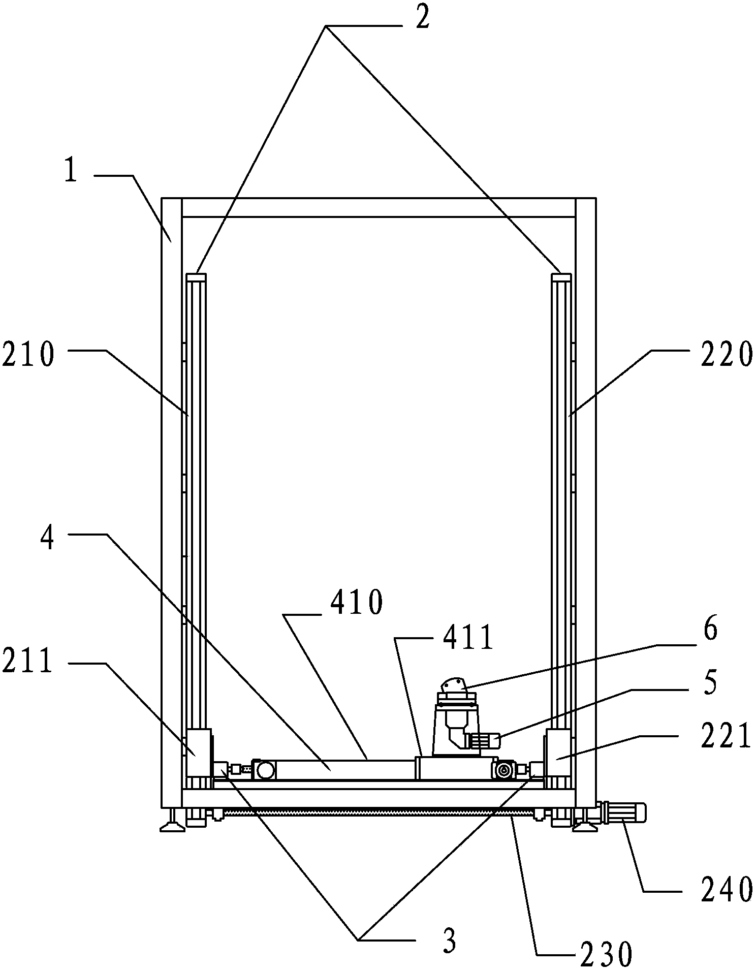
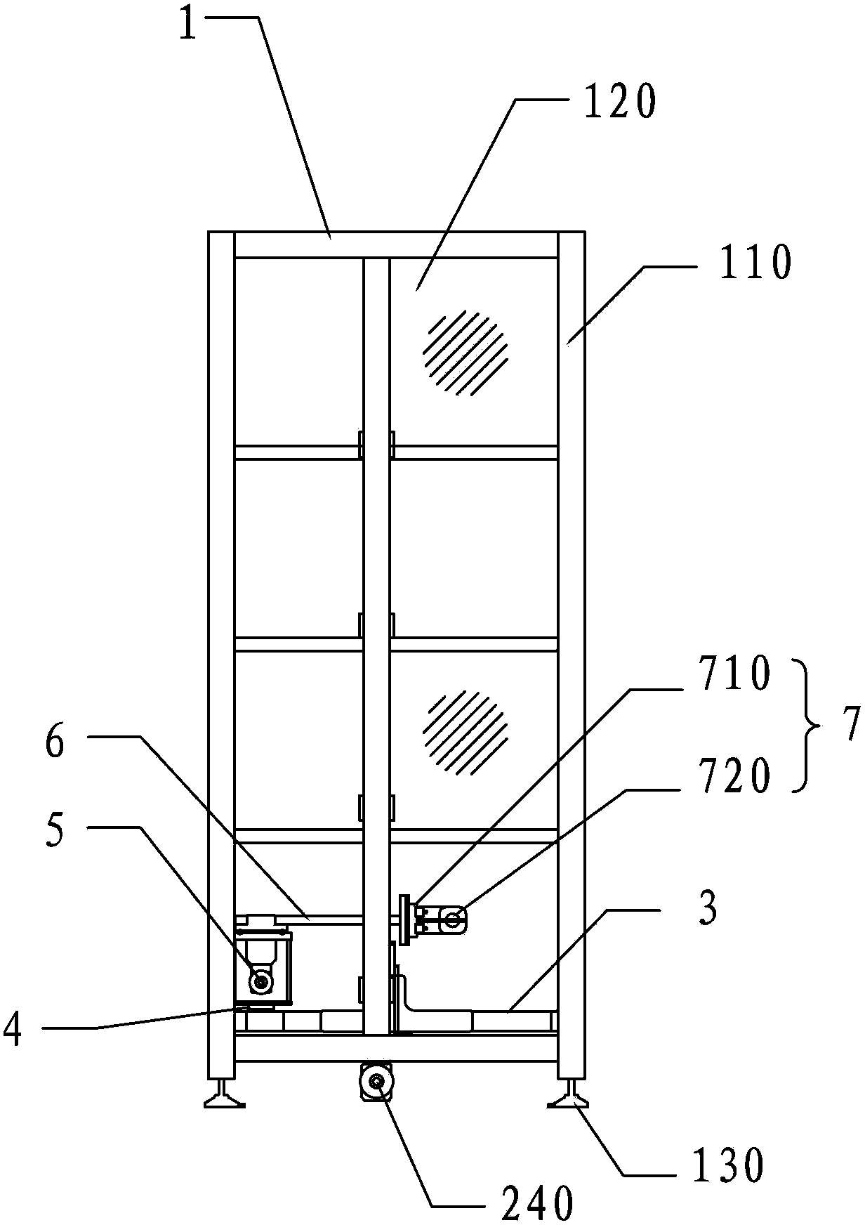
[0022] The invention provides a manipulator gripping machine, please refer to figure 2 , image 3 and Figure 4 , including frame 1, Z-direction linear slide rail group 2, Y-direction linear slide rail group 3, X-direction linear slide rail 4, servo motor four 5, rotating arm 6 and gripper mechanism 7.

[0023] In this embodiment, the frame 1 is in the shape of a "mouth" and is composed of an aluminum alloy frame 110 and an acrylic transparent plate 120 installed in the aluminum alloy frame 110. The bottom of the frame 1 is provided with a foot 130, the foot 130 can be fixed on the ground at the working position to realize the positioning of the frame 1 .

[0024] The Z-direction linear slide rail group 2 includes a first Z-direction rail 210 and a second Z-direction rail ...


PUM


Abstract

The invention discloses a mechanical arm clamping machine which comprises a rack, a Z-direction linear sliding rail set, a Y-direction linear sliding rail set, an X-direction linear sliding rail, a rotation driving device, a rotating arm and a clamping jaw mechanism. The Z-direction linear sliding rail set is arranged on the rack; the Y-direction linear sliding rail set is connected to the inner sides of first and second Z-direction sliding bases on first and second Z-direction guide rails of the Z-direction linear sliding rail set; the X-direction linear sliding rail is connected between first and second Y-direction sliding bases on first and second Y-direction guide rails of the Y-direction linear sliding rail set; the rotation driving device is fixedly arranged on an X-direction sliding base of the X-direction linear sliding rail; one end of the rotating arm is connected to an output shaft of the rotation driving device in the radial direction, and the other end of the rotating arm is fixedly connected with the clamping jaw mechanism. The mechanical arm clamping machine can carry out three-dimensional and high-speed spatial motion and revolving location within a certain range to carry, pick and place products, is suitable for carrying out the operations of carrying, picking and placing in a narrow operating space and among a plurality of operating platforms, and has the advantages of being good in applicability, high in efficiency and low in cost.

Description

technical field [0001] The invention relates to the field of manipulator equipment, in particular to a manipulator gripping machine that is convenient for moving and picking and placing products in a narrow operating space and between multiple operating platforms. Background technique [0002] After assembly of electronic products, electromechanical products, etc., in order to check their potential defects, check their performance reliability and service life, etc., aging (burn-in) tests are required for these products. Aging test is a long-term testing process in which products are transported from the assembly line to high-temperature aging test equipment. Abnormal products during the test will be recorded by monitoring personnel or monitoring instruments. After the test is completed, the abnormal products will be sent for repair to ensure product yield. [0003] figure 1 It is a schematic diagram of the structure of our existing assembly line and 3-layer aging test equi...

Claims


Application Information

Patent Timeline
Patent Type & Authority Applications(China)
IPC IPC(8): B65G47/90
Inventor 林保邦
Owner KUNSHAN HANWEI AUTOMATION EQUIP
Why Eureka
Try Eureka