Drainage mechanism
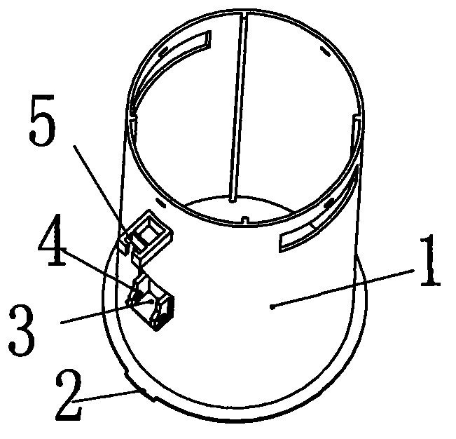
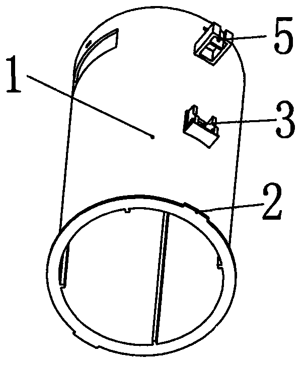
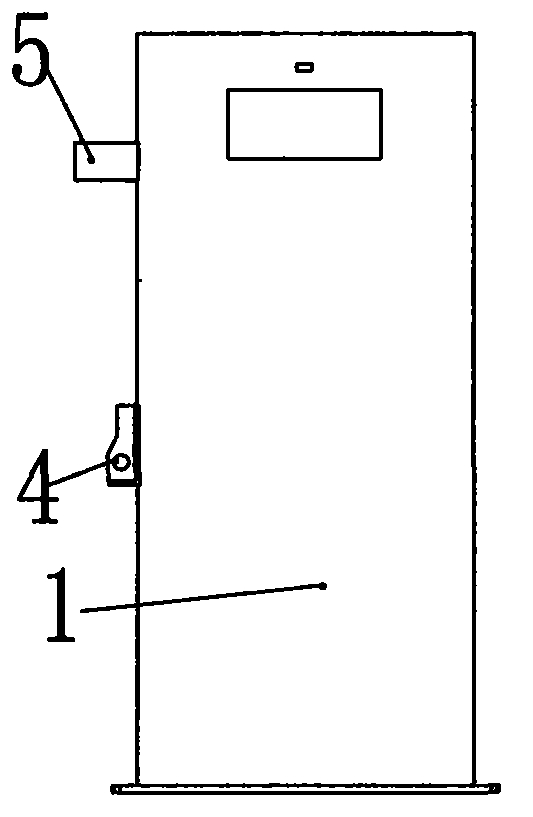
A drainage mechanism and water tank technology, which is applied in water supply devices, flushing equipment with water tanks, buildings, etc., can solve problems such as pressing and not moving, and achieve the effect of easy start-up and drainage, and simple structure
- Summary
- Abstract
- Description
- Claims
- Application Information
AI Technical Summary
Problems solved by technology
Method used
Image
Examples
specific Embodiment approach 2
[0059] When the start button 33 is pressed, one end of the transmission plate 37 rotates downwards, and the other end connected to the transmission rod 40 rotates upwards, driving the transmission rod 40 to move upwards, so that the valve barrel 6 moves upwards, and the water sealing member 15 moves upwards. The valve port of the valve seat 13 is opened, and the locking position 7 on the valve barrel 6 moves to the top of the control head 24, and the control head 24 withstands the locking position 7, as shown in the circle i in the figure.
[0060] Refer to Figure 16(a) for comparison with Figure 10 , Figure 16(b) and Figure 13 The difference between the third embodiment and the first embodiment is that the structure of the water control mechanism 42 in the third embodiment is different from that of the water control mechanism 27 in the first embodiment, and all other parts are the same as those in the first embodiment. The one in the specific embodiment one is exactly the ...
specific Embodiment approach 3
[0061] When the start button 33 is pressed, one end of the transmission plate 37 rotates downwards, and the other end connected to the transmission rod 40 rotates upwards, driving the transmission rod 40 to move upwards, so that the valve barrel 6 moves upwards, and the water sealing member 15 moves upwards. The valve port of the valve seat 13 is opened, the clamping position 7 on the valve cylinder 6 moves to the top of the control head 24, and the control head 24 withstands the clamping position 7, as shown by the circle k in the figure.
[0062] Refer to Figure 17(a) for comparison with Figure 10 , Figure 17(b) and Figure 13 The difference between the fourth embodiment and the first embodiment is that the structure of the water control mechanism 43 in the fourth embodiment is different from the water control mechanism 27 in the first embodiment, and all other parts are the same as those in the first embodiment. The one in the specific embodiment one is exactly the same, ...
specific Embodiment approach 4
[0063] When the start button 33 is pressed, one end of the transmission plate 37 rotates downwards, and the other end connected to the transmission rod 40 rotates upwards, driving the transmission rod 40 to move upwards, so that the valve barrel 6 moves upwards, and the water sealing member 15 moves upwards. The valve port of the valve seat 13 is opened, the clamping position 7 on the valve cylinder 6 moves to the top of the control head 24, and the control head 24 withstands the clamping position 7, as shown in the circle n part in the figure.
[0064] In the present invention, the valve seat 13 can be changed in various ways, such as an existing common valve seat with an overflow pipe; the shape of the valve body 1 and the valve cylinder 6 can be changed in many ways, and can be circular or oval , can also be square or other irregular shapes; the bottom of the valve cylinder 6 can also be designed to be closed, that is, there is no adjustment hole 10. In the present invention...
PUM
 Abstract
Description
Claims
Application Information
 - R&D
- Intellectual Property
- Life Sciences
- Materials
- Tech Scout
- Unparalleled Data Quality
- Higher Quality Content
- 60% Fewer Hallucinations
Browse by: Latest US Patents, China's latest patents, Technical Efficacy Thesaurus, Application Domain, Technology Topic, Popular Technical Reports.
© 2025 PatSnap. All rights reserved.Legal|Privacy policy|Modern Slavery Act Transparency Statement|Sitemap|About US| Contact US: help@patsnap.com


