Heat recovery system

A heat recovery and heat exchanger technology, applied in hot gas variable capacity engine devices, machines/engines, mechanical equipment, etc., can solve problems such as energy loss, and achieve the effect of improving efficiency

Active Publication Date: 2013-12-04
CHINA FIRST AUTOMOBILE
View PDF5 Cites 6 Cited by
  • Summary
  • Abstract
  • Description
  • Claims
  • Application Information

AI Technical Summary

Problems solved by technology

[0004] At the same time, heat engine experts have found that in the process of converting heat energy into mechanical energy in these heat engines, there is energy loss, and usually the proportion of this energy loss accounts for a large part of the total energy of the fuel.

Method used


Image

  • Heat recovery system
  • Heat recovery system
  • Heat recovery system

Examples


Embodiment Construction

[0019] The present invention will be further described below in conjunction with specific drawings.

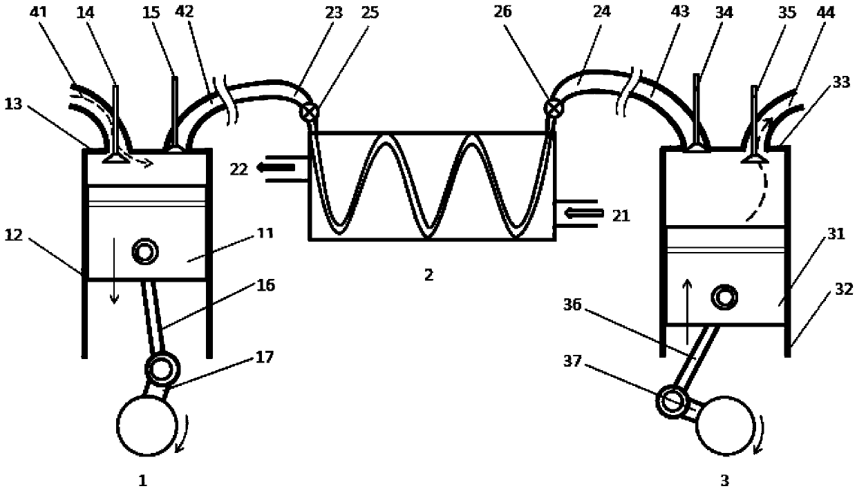
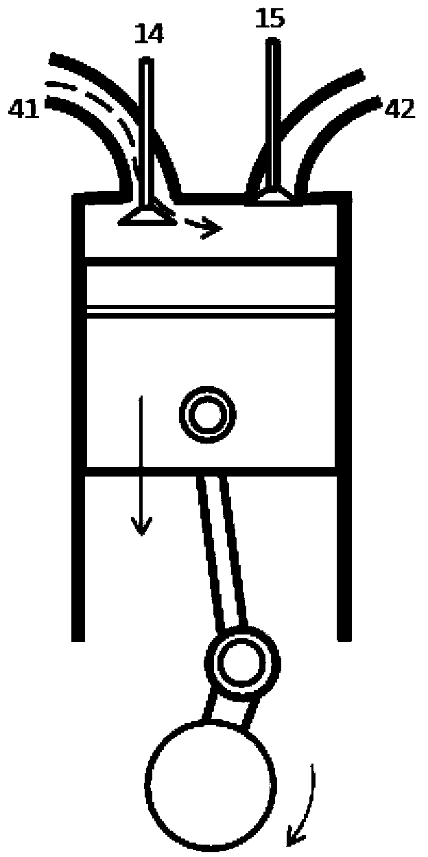
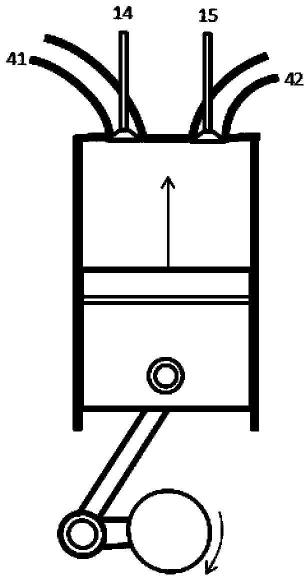
[0020] Such as figure 1 As shown: the heat recovery system includes a compression cylinder 1, a heat exchanger 2, a working cylinder 3, a compression cylinder piston 11, a compression cylinder liner 12, a compression cylinder head 13, a compression cylinder intake valve 14, a compression cylinder exhaust Valve 15, compression cylinder connecting rod 16, compression cylinder crankshaft 17, heat source inlet 21, heat source outlet 22, working gas inlet 23, working gas outlet 24, first valve 25, second valve 26, working cylinder piston 31, working cylinder Sleeve 32, working cylinder head 33, working cylinder intake valve 34, working cylinder exhaust valve 35, working cylinder connecting rod 36, working cylinder crankshaft 37, intake pipeline 41, first connecting pipeline 42, second connecting pipe Road 43, exhaust pipeline 44 and so on.

[0021] Such as figure 1 As shown, the...


PUM


Abstract

The invention relates to a heat recovery system which comprises a compressing cylinder, an acting air cylinder and a heat exchanger. The heat recovery system is characterized in that a heat source inlet, a heat source outlet, a working gas inlet and a working gas outlet are formed in the heat exchanger, a compressing cylinder inlet and a compressing cylinder discharge port are formed in the compressing cylinder, the compressing cylinder inlet and the compressing cylinder discharge port are provided with a compressing cylinder air inlet valve and a compressing cylinder discharge valve respectively, an acting air cylinder air inlet and an acting air cylinder discharge port are formed in the acting air cylinder, the acting air cylinder air inlet and the acting air cylinder discharge port are provided with an acting air cylinder air inlet valve and an acting air cylinder discharge valve respectively, the compressing cylinder discharge port is communicated with the working gas inlet of the heat exchanger through a first communication pipeline, and the working gas outlet of the heat exchanger is communicated with the acting air cylinder air inlet through a second communication pipeline. The heat recovery system can effectively convert part of heat which is not used by various heat engines into mechanical energy, and therefore efficiency of existing heat engines can be improved.

Description

technical field [0001] The invention relates to a heat recovery system, in particular to a heat engine which can be applied to sea, land, air and other means of transportation to effectively convert heat energy from a heat source into mechanical energy. Background technique [0002] A traditional heat engine burns one or more fuels, and the fuel releases heat energy. The heat engine uses part of the heat energy, and then transmits this part of energy to the outside world through the mechanical movement of the parts to become mechanical energy, realizing the transformation from heat energy to mechanical energy. convert. The ratio of this part of energy transmitted to the outside to the energy of the fuel itself is called the efficiency of energy utilization of this kind of heat engine. [0003] Over the years, heat engine experts have conducted research on various technologies to improve the efficiency of heat engine energy utilization. What we can see in internal combustion...

Claims


Application Information

Patent Timeline
Patent Type & Authority Applications(China)
IPC IPC(8): F02G1/043F02G1/053
Inventor 张艳辉陈勤学韩小强
Owner CHINA FIRST AUTOMOBILE
Why Eureka
Try Eureka