Diagnosis method for heat radiation system

A heat dissipation system and diagnostic method technology, applied in vehicle testing, machine/structural component testing, measuring devices, etc., can solve problems such as complex structure and additional cost, and achieve the effect of low cost and simple structure

Active Publication Date: 2013-12-04
UNITED AUTOMOTIVE ELECTRONICS SYST
View PDF5 Cites 18 Cited by
  • Summary
  • Abstract
  • Description
  • Claims
  • Application Information

AI Technical Summary

Problems solved by technology

This device needs to add additional components in the water cooling system, which not only complicates the structure, but also increases additional costs

Method used


Image

  • Diagnosis method for heat radiation system
  • Diagnosis method for heat radiation system

Examples


Embodiment Construction

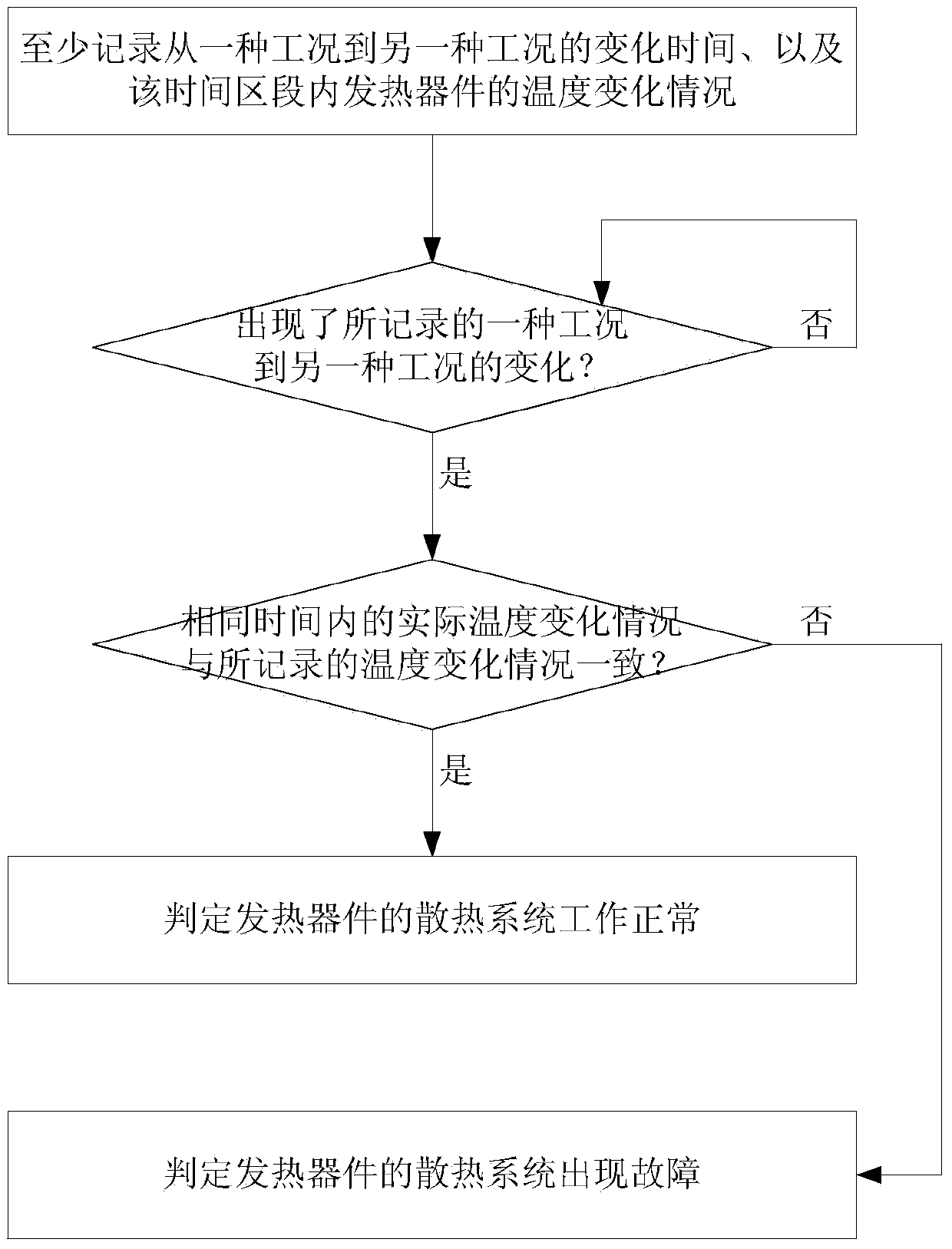
[0014] The application scenario of this application is: the heat of the heating device is radiated and cooled by the heat dissipation system, and the temperature of the heating device is detected in real time by a temperature sensor. see figure 1 , the diagnosis method of the cooling system of this application is:

[0015] In the first step, a certain state of the physical quantity that causes the heat generation of the heat-generating device to change is called a working condition, and at least record the time for changing from one working condition to another and the temperature detected by the temperature sensor. The temperature change during this time period;

[0016] Step 2, when the heating device is in one recorded working condition to another working condition, compare the actual temperature change detected by the temperature sensor within the same time period with the recorded temperature change;

[0017] When the two match, it is determined that the heat dissipatio...


PUM


Abstract

The application discloses a diagnosis method for a heat radiation system. The heat radiation system is used for cooling a heating device, and the temperature of the heating device is detected by a temperature sensor in real time. The diagnosis method comprises the following steps of: step 1, calling one state of a physic value which causes change of a heating value of the heating device as a working condition, at least recording time taken for the change from one working condition to another working condition, and a temperature change condition detected by a temperature sensor within the time section; step 2, when the heating device is changed from the recorded one working condition to the recorded other working condition, comparing the practical temperature change condition detected by the temperature sensor within the same time with the recorded temperature change condition; when the two change conditions are consistent, determining that the heat radiation system of the heating device works normally; when the two change conditions are inconsistent, determining that the heat radiation system of the heating device is in fault, and sending out an alarm signal or carrying out fault treatment. The diagnosis method for the heat radiation system has low cost and can cover all types of faults of the heat radiation system.

Description

technical field [0001] The present application relates to a method for detecting whether the cooling system of a heating device works normally. Background technique [0002] In order to ensure the normal operation and service life of the heating device, a heat dissipation system is usually provided for the heating device. The heating device transfers heat to the heat dissipation system through good contact with the heat dissipation system, and the heat dissipation system uses air cooling or water cooling to take away the heat. The calorific value of some heating devices changes at any time. Although there is a temperature sensor to directly detect the temperature of the heating device, it is impossible to know whether the cooling system is working normally based on the temperature value. [0003] For example, drive motors, motor controllers, and DC / DC (direct current-direct current) conversion circuits of new energy vehicles (pure electric vehicles, hybrid vehicles, etc.) a...

Claims


Application Information

Patent Timeline
IPC IPC(8): G01M99/00G01M17/007
Inventor 刘强景来军
Owner UNITED AUTOMOTIVE ELECTRONICS SYST
Why Eureka
Try Eureka