Eureka AIR delivers breakthrough ideas for toughest innovation challenges, trusted by R&D personnel around the world.

Seepage failure testing device and method for seam pipeline between pipe bags and dam bags

A destructive test and tube-bag dam technology, which is applied in the direction of measuring devices, soil material testing, material inspection products, etc., can solve the problems of dam safety hazards, seepage damage, etc., and achieve the effects of low processing cost, convenient operation, and simple installation

Inactive Publication Date: 2013-12-04
HOHAI UNIV
View PDF6 Cites 17 Cited by
  • Summary
  • Abstract
  • Description
  • Claims
  • Application Information

AI Technical Summary

Problems solved by technology

[0005] like figure 1 As shown, the pipe-bag dam is generally composed of multiple layers of sand-filled pipe bags, and there are slender joints between the pipe bags. In the case of no protection during the construction period and insufficient protection after construction, Due to the long-term action of the water pressure difference caused by the fluctuation of the water level inside and outside the pipe bag dam and the fluctuating water flow formed by waves, there is a risk of the dam core filling being washed away by the water flow, which brings hidden dangers to the safety of the dam body.
At present, there is no research on the phenomenon of seepage and failure of the bag-filled dam core filling sand through the bag-filled joint pipeline under the action of water flow and waves.

Method used


Image

  • Seepage failure testing device and method for seam pipeline between pipe bags and dam bags
  • Seepage failure testing device and method for seam pipeline between pipe bags and dam bags
  • Seepage failure testing device and method for seam pipeline between pipe bags and dam bags

Examples


Embodiment Construction

[0022] The technical scheme of the present invention is described in detail below in conjunction with accompanying drawing:

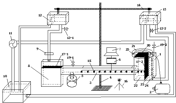
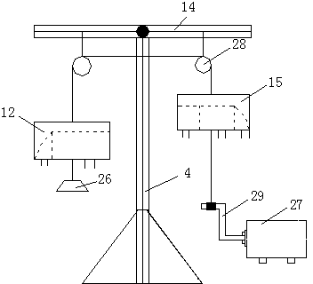
[0023] Such as figure 2 As shown, a pipe-bag-dam-bag seam pipeline penetration damage test device includes a support 4, and a cantilever 14 is arranged horizontally on the upper part of the support 4. One end of the cantilever 14 is connected to the water outlet tank 12, and the other end is connected to the water inlet tank 15; the water outlet tank 12 The lower end of the hose is connected to the suspended mass sand collection tank 8, the lower end hose of the water inlet tank 15 is connected to the sand tank 1, the suspended mass sand collection tank 8 and the sand tank 1 are connected to the water tank 3, and is close to the suspended mass sand collection tank 8 The water tank 3 on one side is connected with the moving mass sand collection tank 5, and the pipe bag fabric is pasted on the inner wall of the water tank 3, and several water pressure se...


PUM


Abstract

The invention discloses a seepage failure testing device and method for a seam pipeline between pipe bags and dam bags, and relates to the field of physical model tests of water conservancy projects. The device adopts the structure that a cantilever is horizontally arranged at the upper part of a support, one end of the cantilever is connected with a water-outlet tank, and the other end of the cantilever is connected with a water-inlet tank; a lower-end hose of the water-outlet tank is connected with a suspended load sand-collecting tank, and a lower-end hose of the water-inlet tank is connected with a sand tank; a water tank is connected between the suspended load sand-collecting tank and the sand tank, a bed load sand-collecting tank is connected to the water tank near one side of the suspended load sand-collecting tank, pipe bag fabric is stuck on the inner wall of the water tank, a plurality of water pressure sensors are arranged in the water tank, and are connected with a data collecting card, and the output end of the data collecting card is connected with a computer; a sand filling chamber, a steady flow chamber and a water inlet chamber are sequentially arranged from one side near the water tank to one side far away from the water tank in the sand tank. The seepage failure testing device and the testing method realize the purposes of simple device, convenience in operation and low processing cost, are economic and applicable, and are suitable for small physical model tests.

Description

[0001] technical field [0002] The invention relates to a test device and test method for seepage damage of pipe-bag dam joints between bags. The device is used for simulating the process of seepage damage to the pipe-bag dam dam core filling sand body passing through the bag-joint seam pipes by tidal currents and waves , which belongs to the field of hydraulic engineering physical model experiments. [0003] Background technique [0004] With the rapid economic development of my country's coastal areas, pipe bag dams are increasingly used as reservoir dams in estuaries and reclamation dams in coastal ports. Filling pipe bag dam building technology began in the 1950s and 1960s. my country has gone from Hong Kong International Airport, Pudong International Airport, and Yangtze River Estuary waterway regulation to coastal reclamation and estuary storage in Jiangsu, Shanghai, Zhejiang, Fujian and other provinces and cities. A large number of estuary and coastal projects su...

Claims


Application Information

Patent Timeline
IPC IPC(8): G01N33/24G01N13/04
Inventor 曹明杰束一鸣蔚成亮宋倩张宪雷
Owner HOHAI UNIV
Why Eureka
Eureka Blog
Learn More