Reinforcing method and reinforcing structure for water-rich sand layer geological shield receiving end

A water-rich sand layer and reinforcement structure technology, applied in underground chambers, earthwork drilling, wellbore lining, etc., can solve the problems of high investment cost, uneconomical, and increased shield construction period, etc., to improve the strength of the surrounding soil , Improve the effect of reinforcement

Pending Publication Date: 2021-10-22
CCCC TUNNEL ENG +1
View PDF7 Cites 1 Cited by
  • Summary
  • Abstract
  • Description
  • Claims
  • Application Information

AI Technical Summary

Problems solved by technology

In high-water-rich strata, water gushing and leakage often occur due to poor reinforcement quality, which seriously leads to soil collapse and failure of shield tunnel reception
[0003] The traditional shield end reinforcement method has the following deficiencies: 1. The water-rich sand and pebble layer is characterized by high water-rich, large permeability coefficient, high pebble strength, and uneven gradation. Difficulty, groundwater dilution, stringing grout and grouting bodies are difficult to uniform, etc., resulting in unsatisfactory reinforcement effects; 2 Completely use high-pressure rotary grouting piles or grouting to strengthen the formation, if you want to achieve the reinforcement effect, the input cost is high, which is not economical; 3 The water-stopping and waterproofing effect is poor, and it is easy to leak water and sand gushing, which increases the risk of shield tunneling construction and increases the construction period of shield tunneling tunnel

Method used


Image

  • Reinforcing method and reinforcing structure for water-rich sand layer geological shield receiving end
  • Reinforcing method and reinforcing structure for water-rich sand layer geological shield receiving end
  • Reinforcing method and reinforcing structure for water-rich sand layer geological shield receiving end

Examples


Embodiment 2

[0040] A method for reinforcing a receiving end of a geological shield in a water-rich sand layer, specifically comprising the following steps:

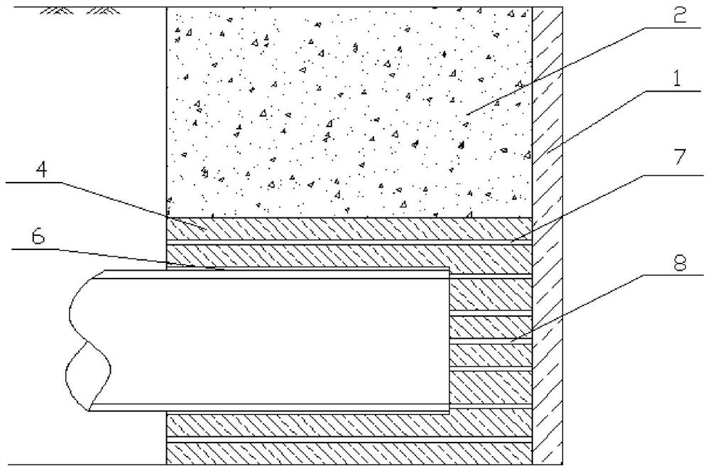
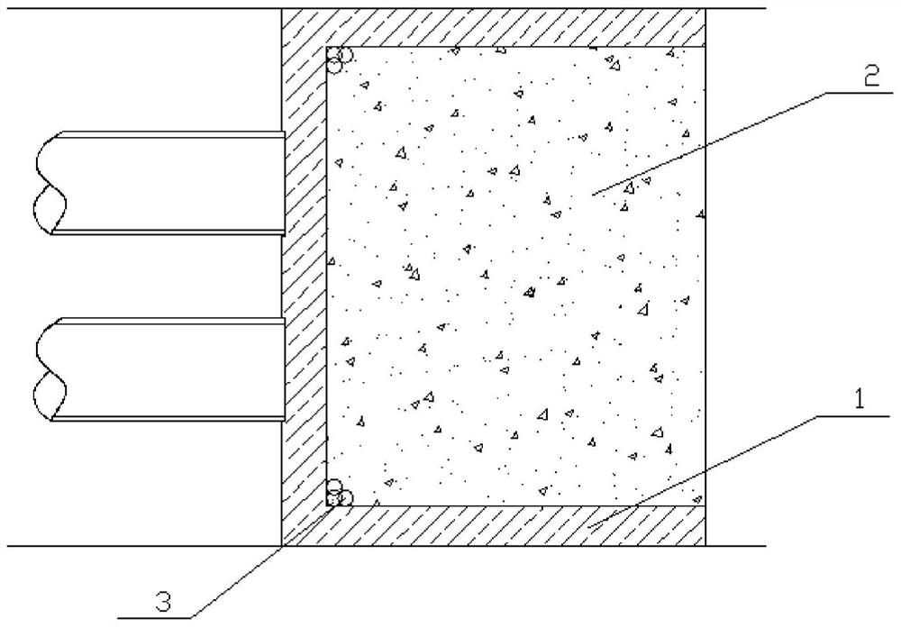
[0041] (1) Design of the enclosure structure: pouring plain concrete around the receiving end of the shield to form an underground continuous wall with a concave outer structure;

[0042] (2) Layered reinforcement design:

[0043] Implement local freezing design in the depth direction and length direction from the shield tunnel vault 3-5m to the vault bottom 3-5m; carry out the three-axis mixing pile reinforcement design in the depth direction length direction from the ground to the shield tunnel vault 3-5m;

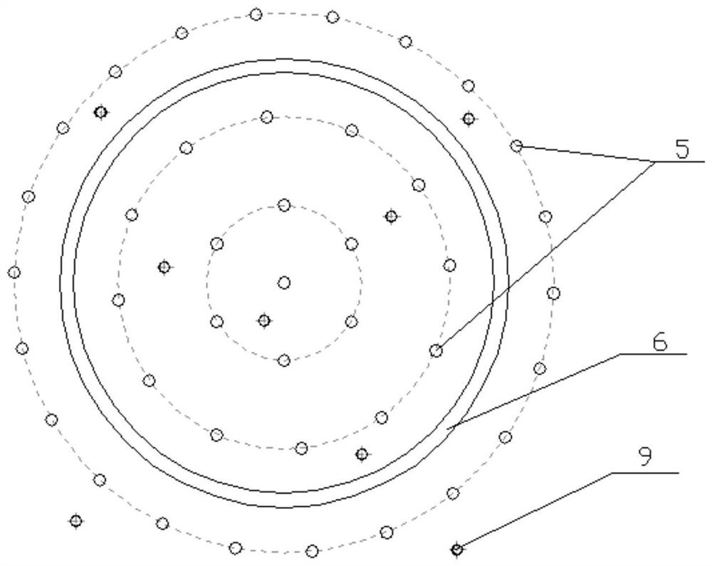
[0044]S1. Freezing design: install a horizontal freezing tube at the receiving end of the shield, the freezing tube is parallel to the advancing direction of the shield, the freezing tube is connected to an external freezing source, and forms a horizontal freezing reinforcement area around the freezing tube;

[0045] The lengt...


PUM


Abstract

The invention discloses a reinforcing method and a reinforcing structure for a water-rich sand layer geological shield receiving end. The reinforcing method and the reinforcing structure are used for carrying out layered reinforcement on a soil body around the shield receiving end and comprise the following steps of firstly, designing a horizontal freezing reinforcement mode, and freezing the soil body around the shield receiving end into a freezing reinforcement area with a concave structure by utilizing the matching of a long freezing pipe and a short freezing pipe so as to improve the strength of the surrounding soil body, achieve a water stop effect and help to improve a grouting or jet grouting reinforcement effect, therefore a three-shaft stirring pile reinforcing area is arranged above the freezing reinforcement area, the shield end is further reinforced, and the situation that the reinforcing effect of the shield end is affected again by water in soil after freezing is completed is avoided. The construction of the three-shaft stirring pile reinforcing area on the upper layer and the construction of the horizontal freezing reinforcing area do not influence each other, compared with a vertical freezing reinforcing mode, the reinforcing effect is higher, the reinforcing efficiency is higher, and safe receiving of a shield tunneling machine is ensured.

Description

technical field [0001] The invention relates to the technical field of tunnel construction, in particular to a reinforcement method and a reinforcement structure for a receiving end of a geological shield in a water-rich sand layer. Background technique [0002] With the continuous development of urban rail transit in my country, the urban underground space has been rapidly developed and utilized, and the construction of underground tunnels has entered a peak period. Shield construction has the advantages of good safety, high degree of mechanization, fast excavation speed, and little environmental disturbance. Due to its wide adaptability and other advantages, it has been rapidly promoted and applied in the fields of urban rail transit, highway tunnels, municipal pipelines, etc., and shield tunneling method is used in a large number of engineering constructions. During shield construction, it is necessary to reinforce the end of the shield tunnel. In high water-rich formatio...

Claims


Application Information

Patent Timeline
Patent Type & Authority Applications(China)
IPC IPC(8): E21D9/06E21D9/00E21D11/10E21D11/38
CPCE21D9/06E21D9/001E21D9/003E21D11/10E21D11/38
Inventor 张四俊周峰康飞魏涛惠海鹏尚冰郭文学
Owner CCCC TUNNEL ENG
Why Eureka
Try Eureka