Ultra-micro micro-beam-tube type optical cable

An ultra-miniature, tube-type technology, applied in the field of communication optical cables, can solve the problems of inability to achieve ultra-miniature optical cables, low tensile performance of optical cables, and excessively large outer diameter of optical cables, and achieve high tensile performance and excellent attenuation transmission Performance and temperature performance, space resource saving effect

Inactive Publication Date: 2013-12-04
成都亨通光通信有限公司
View PDF7 Cites 2 Cited by
  • Summary
  • Abstract
  • Description
  • Claims
  • Application Information

AI Technical Summary

Problems solved by technology

[0003] Chinese patent application number: CN201220611270 discloses a low-friction optical fiber bundle micro-optic cable, including an outer sheath, the outer sheath is coated with an optical fiber bundle, and the optical fiber bundle is coated with a bundle-shaped optical fiber with a binder It is formed by solidification, and the outer surface of the outer sheath is provided with longitudinal grooves along the circumference. Such an optical cable is light in weight and easy to strip, and is suitable for application in metropolitan area networks and access networks. However, this optical cable is resistant to Very low tensile properties
[0004] Chinese patent application number: CN201220318097 discloses a fully dry miniature air-blown optical cable, including an optical fiber, a sleeve, and an outer sheath. The optical fiber is arranged in the inner cavity of the sleeve, and the outer sheath covers the sleeve. Water, dry-type water-blocking material is set in the inner cavity of the sleeve. Such an optical cable uses dry-type water-blocking material for waterproofing,

Method used


Image

  • Ultra-micro micro-beam-tube type optical cable

Examples


Embodiment Construction

[0018] The technical solution of the present invention will be further described in detail below in conjunction with the accompanying drawings, but the protection scope of the present invention is not limited to the following description.

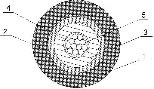
[0019] Such as figure 1 Shown, a kind of ultra-miniature micro-bundle tube type optical cable, it comprises the optical fiber bundle 5 that one or more optical fibers are formed, loose tube 3, strengthens filling layer 2 and outer sheath 1, and described optical fiber bundle 5 is positioned at loose Fiber paste 4 is filled inside the tube 3 and between the fiber bundles inside the loose tube 3 , and the outer side of the loose tube 3 is wrapped by a reinforced filling layer 2 , and the outermost layer of the reinforced filling layer 2 is an outer sheath 1 .

[0020] The number of optical fibers contained in the optical fiber bundle 5 is 2-12, and the number of optical fibers can be adjusted according to actual conditions.

[0021] The rein...


PUM

PropertyMeasurementUnit
Diameteraaaaaaaaaa

Abstract

The invention discloses an ultra-micro micro-beam-tube type optical cable. The ultra-micro micro-beam-tube type optical cable comprises optical fiber beams (5) which are formed by one or a plurality of optical fibers, a loose sleeve pipe (3), a reinforced packing layer (2) and an external protective sleeve (1); the optical fiber beams (5) are arranged on the internal side of the loose sleeve pipe (3); fiber paste (4) is filled between the optical fiber beams which are arranged inside the loose sleeve pipe (3); the reinforced packing layer (2) wraps the external side of the loose sleeve pipe (3); the external protective sleeve (1) is arranged at the outermost layer of the reinforced packing layer (2). The ultra-micro micro-beam-tube type optical cable is small in occupation space and the wiring arrangement number of optical cable during the wiring arrangement is increased due to the fact that the diameter of the external protective sleeve is not more than 2.3 mm, meanwhile low in price due to the fact that the reinforced layer is weaved by high intensity glass fibers, meanwhile provided with rat proof and anti-thunder performances and easy to be paved due to the fact that the external diameter is small.

Description

technical field [0001] The invention relates to a communication optical cable technology, in particular to an ultraminiature micro-bundle tube type optical cable. Background technique [0002] The traditional pipe laying method is generally to put several plastic pipes with an outer diameter of 2-8cm in the concrete pipe hole at the same time, and put an optical cable in each plastic pipe, which leads to the use of optical cables for communication pipes. The number is not high. With the continuous shortage of urban pipeline resources, the micro-pipe and micro-cable air blowing deployment technology that has emerged in recent years has become more and more mature. The air-fed micro-cable system uses a combination of an empty duct bundle containing multiple sub-tubes and very light-weight micro-cables that can be installed at any time. The micro-optical cable with one or more cores in the tube can be easily installed in the direct-buried micro-tube, which doubles the utiliza...

Claims


Application Information

Patent Timeline
IPC IPC(8): G02B6/44
Inventor 孙义兴彭志勇许建国李涛赵坤祥
Owner 成都亨通光通信有限公司
Why Eureka
Try Eureka