
Method of automatically adjusting voltage level and voltage level adjusting device thereof

A technology of voltage level and adjustment devices, which is applied in the direction of adjusting electrical variables, control/regulation systems, and high-efficiency power electronics conversion, etc. It can solve problems such as poor small signal recognition ability, level accuracy deviation, and loss of signal transmission capabilities.

Active Publication Date: 2013-12-04
FU TONG TECH
View PDF7 Cites 29 Cited by
  • Summary
  • Abstract
  • Description
  • Claims
  • Application Information

AI Technical Summary

Problems solved by technology

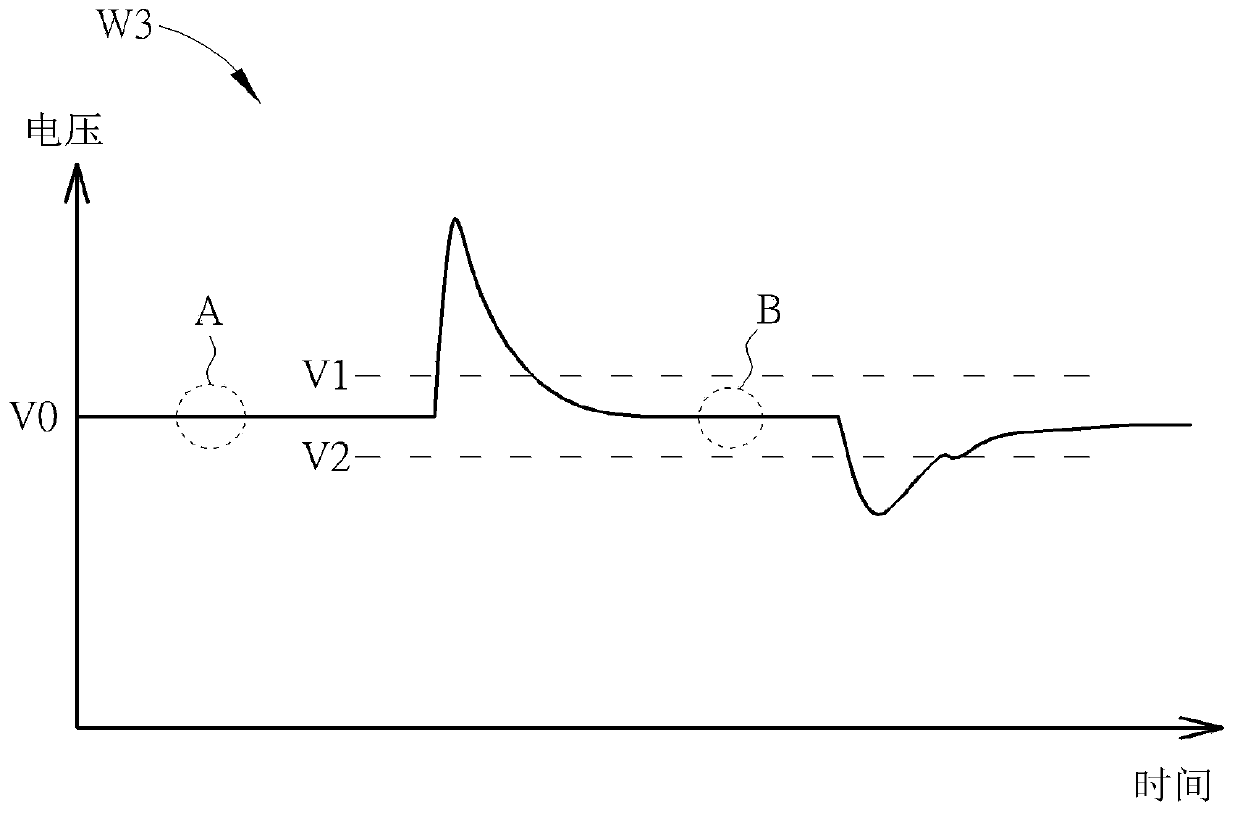
[0003] However, there are deficiencies in the existing technology: first, the carrier signal on the power supply coil is transmitted to the signal analysis circuit and then undergoes half-wave rectification processing, that is, half of the signal variation has been attenuated. Under the circuit without signal amplification, Its small signal recognition ability is poor; second, the reference voltage of the comparator is the reference voltage level generated by connecting the power terminal and the ground terminal with two voltage dividing resistors, and the resistance component itself has errors during production, which may cause the design The level accuracy of the determination is deviated. Considering the production yield, it is impossible to set the reference voltage too close to the normal voltage of the signal, so as to avoid the error output of the signal due to component errors, and because the reference voltage cannot be set It is set close to the normal voltage, resulting in poor signal discrimination sensitivity; third, in the prior art, in order to trigger discrimination in both positive phase and negative phase of the signal, two comparators and two reference voltages are required It is used for up and down triggering of signals, but because of the error problem of components, it is more difficult to produce and set; fourth, in the prior art, only the trigger signal from the power receiving end can be judged and analyzed into digital data codes, but it cannot Interpret the data signal strength. When the data signal is weak, it is impossible to increase the energy in time to improve the signal strength. When the coil coupling condition is not good, it is easy to lose the signal transmission ability.

Method used


Image

  • Method of automatically adjusting voltage level and voltage level adjusting device thereof
  • Method of automatically adjusting voltage level and voltage level adjusting device thereof
  • Method of automatically adjusting voltage level and voltage level adjusting device thereof

Examples


Embodiment Construction

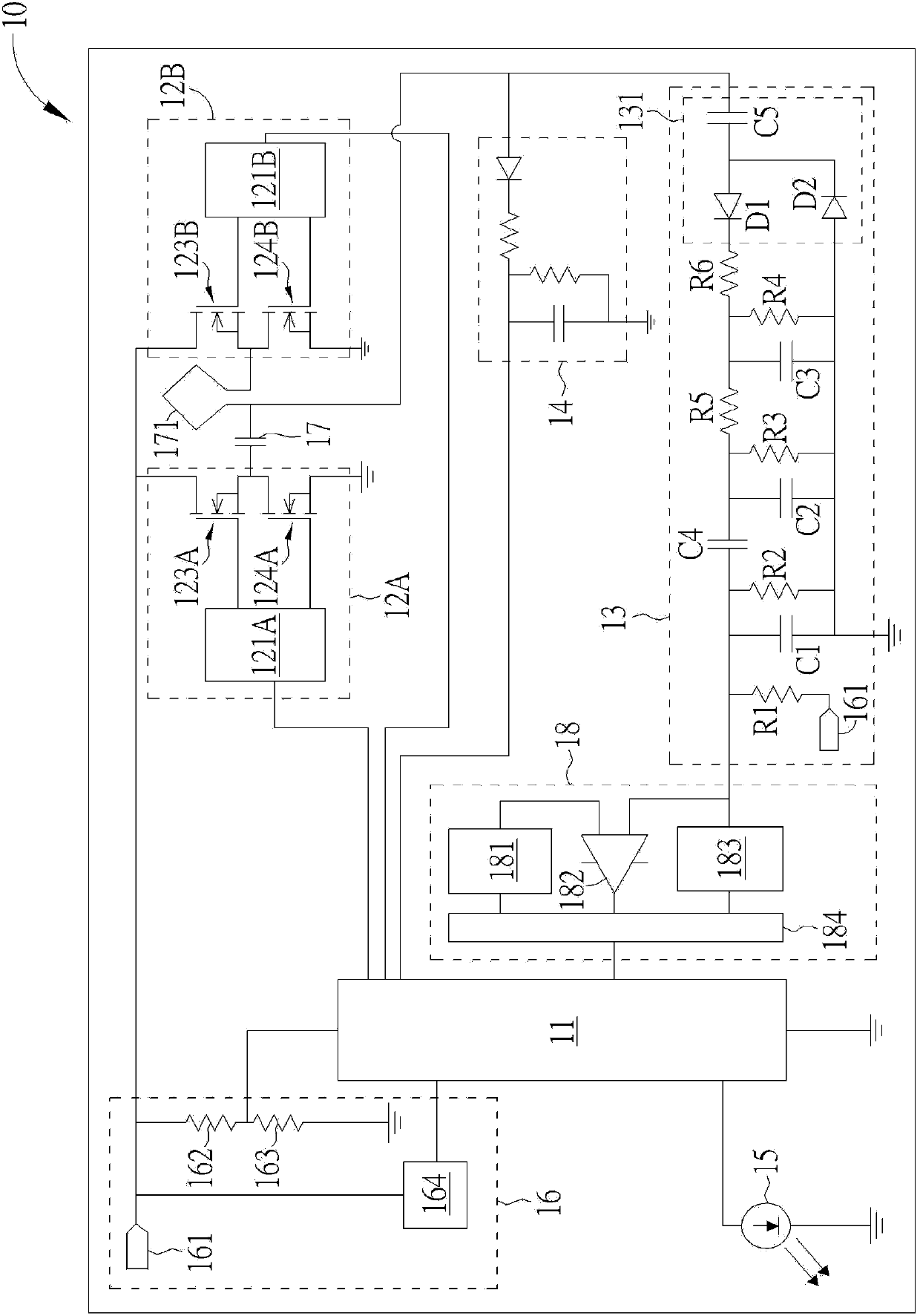
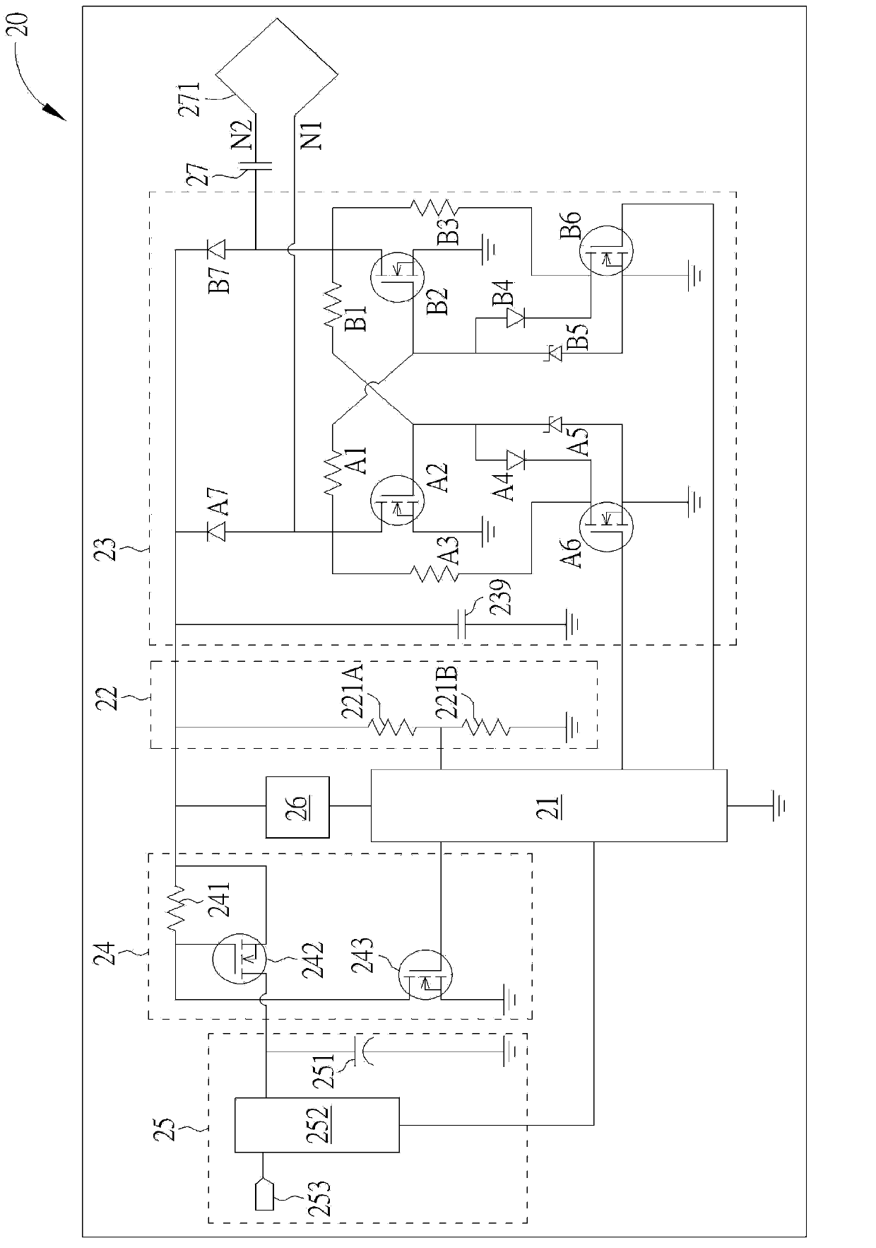
[0073] Please refer to figure 1 , figure 1 It is a schematic diagram of a power supply module 10 of an inductive power supply according to an embodiment of the present invention. Such as figure 1 As shown, the power supply module 10 includes a power supply microprocessor 11, power supply drive units 12A and 12B, a signal analysis circuit 13, a voltage detection circuit 14, a display unit 15, a power supply unit 16, a resonant capacitor 17, a power supply The coil 171 and a voltage level adjusting device 18 . The power supply microprocessor 11 is electrically connected to the power supply drive units 12A and 12B, the voltage detection circuit 14 , the display unit 15 , the power supply unit 16 and the voltage level adjustment device 18 for controlling various operations of the power supply module 10 . The power supply driving unit 12A includes a driving device 121A, an upper bridge switch assembly 123A and a lower bridge switch assembly 124A, and the power supply driving uni...


PUM


Abstract

A method of automatically adjusting a voltage level used in an induction type power supply system includes detecting an output voltage of a signal analysis circuit; adding a first threshold value to the output voltage to generate a first determination voltage and subtracting a second threshold value from the output voltage to generate a second determination voltage; outputting the first determination voltage as a reference voltage; and comparing a trigger signal of the signal analysis circuit and the reference voltage, in order to generate a first data code; wherein when the step of comparing the trigger signal of the signal analysis circuit and the reference voltage in order to generate the first data code fails, the method further includes outputting the second determination voltage as the reference voltage and comparing the trigger signal of the signal analysis circuit and the reference voltage, in order to generate a second data code.

Description

technical field [0001] The present invention relates to a method for automatically adjusting the voltage level of an inductive power supply and its voltage level adjusting device, in particular to a method that can amplify the feedback signal strength in the inductive power supply to improve signal discrimination A sensitivity automatic voltage level adjustment method and a voltage level adjustment device thereof. Background technique [0002] In the inductive power supply, in order to operate safely, it is necessary to confirm that the power supply coil is the correct power receiving device at the supply end, and only send power when it can receive power. In order to identify whether it is correct at the power supply end The power receiving device needs to be identified through data code transmission. The transmission of the data code is to drive the power supply coil to generate resonance through the power supply end, and transmit the electromagnetic energy to the power r...

Claims


Application Information

Patent Timeline
IPC IPC(8): G05F1/56
CPCY02B70/1433
Inventor 蔡明球詹其哲
Owner FU TONG TECH
Learn More