Supercharge Your Innovation With Domain-Expert AI Agents!

Control system of optical touch screen

An optical touch screen and control system technology, applied in the input/output process of data processing, instruments, electrical digital data processing, etc., can solve the problems of complex control methods and high clock accuracy requirements, avoid high light effects, and reduce energy consumption. Effect

Inactive Publication Date: 2013-12-04
BEIJING UNITOP NEW TECH CO LTD
View PDF5 Cites 14 Cited by
  • Summary
  • Abstract
  • Description
  • Claims
  • Application Information

AI Technical Summary

Problems solved by technology

[0010] The technical problem to be solved by the present invention is that the optical touch screen using passive light sources in the prior art has complex control methods when different cameras work at different times, and the clock accuracy is too high, so as to provide a simple and easy optical touch screen control system

Method used


Image

  • Control system of optical touch screen
  • Control system of optical touch screen
  • Control system of optical touch screen

Examples


Embodiment 1

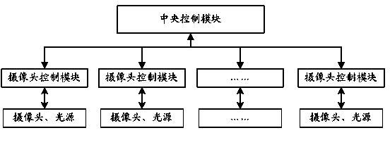
[0043] This embodiment provides a control system for an optical touch screen, such as figure 2 As shown, it includes: a central control module; at least two groups of camera control modules, each group of camera control modules includes at least one camera control module, and each of the camera control modules is used to control the opening or closing of a camera; the central The control module sends control instructions to all camera control modules in each group at different times; different camera control modules control the corresponding cameras to work after receiving the control instructions.

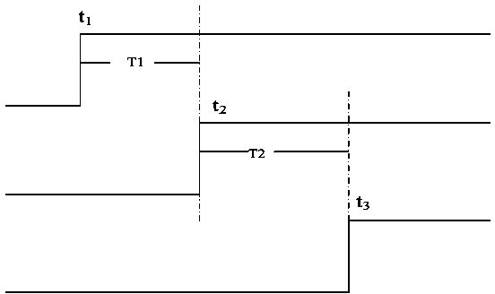
[0044] With the solution of this embodiment, it is only necessary for the central control module to issue control commands at different times, so an accurate clock signal is not required in the central control module, and it is only necessary to be able to distinguish between different camera control modules A logical clock that controls time is sufficient. For example, if an ed...

Embodiment 2

[0055] On the basis of Example 1, such as Image 6 As shown, each camera control module in this embodiment includes a synchronization control unit, a camera controller, a memory and an image processing unit. The synchronization control unit is configured to reset its corresponding camera after receiving the control instruction sent by the central control module. The camera controller is used to receive the image data output by the camera; the memory is used to store the image data received by the camera controller; the image processing unit is used to read the image data from the memory and Send the image data to the central control module after processing.

[0056] For the optical touch screen, the camera will output image data at a fixed frame rate after startup, and the camera will reset after receiving the reset command from the synchronization control unit, and the behavior after startup can be implemented after a fixed time. Therefore, for different cameras in the same...


PUM


Abstract

The invention provides a control system of an optical touch screen. A central control module sends control commands to each set of camera control modules at different moments, each camera control module controls the operation of a corresponding camera after receiving the control commands, and when a set of cameras works, the central control module turns on or lightens light sources corresponding to the set of cameras and turns off or dims light sources opposite to the set of cameras. According to the technical scheme, the central control module sends the control commands to the camera control modules at different moments to control different cameras to work in a time-staggered mode. The control method is simple and has high precision. Moreover, due to the fact that when a certain camera works, the opposite light sources are turned off or dimmed, highlight influence of other light sources on shooting of the camera is effectively avoided, and energy consumption of the optical touch screen is lowered to some extent.

Description

technical field [0001] The invention relates to an optical touch system, in particular to a system for realizing camera control in an optical touch screen with multiple cameras, and belongs to the field of optical touch screen applications. Background technique [0002] The retro-reflective light source touch screen based on two cameras has many advantages such as simple structure, low cost, good touch and writing performance, and easy production. It has been widely recognized in recent years and occupies a large share in large and medium-sized touch screens. Its structure is as figure 1 As shown in the figure, the light emitted from the LED light set in the upper left corner of the touch screen frame is reflected by the reflective strip installed on the touch screen frame, and then enters the CCD camera in the upper right corner of the top. In the same way, the light emitted by the LED light in the upper right corner of the top is transmitted to the CCD camera on the left ...

Claims


Application Information

Patent Timeline
IPC IPC(8): G06F3/042
Inventor 王宇辉吴振宇刘新斌
Owner BEIJING UNITOP NEW TECH CO LTD
Features
  • R&D
  • Intellectual Property
  • Life Sciences
  • Materials
  • Tech Scout
  • Unparalleled Data Quality
  • Higher Quality Content
  • 60% Fewer Hallucinations
Learn More