Capacitive touch screen and manufacturing method thereof

A technology of capacitive touch and production method, which is applied in the direction of electrical digital data processing, instrumentation, input/output process of data processing, etc., and can solve problems such as long conductive lines, difficult touch operation, and large line resistance

Inactive Publication Date: 2013-12-04
WUHU TOKEN SCI
View PDF5 Cites 16 Cited by
  • Summary
  • Abstract
  • Description
  • Claims
  • Application Information

AI Technical Summary

Problems solved by technology

[0011] OGS refers to a glass solution, which is an integrated structure of a glass cover and an ITO conductive sensor; the structures of the above touch screens have their own characteristics, some have high hardness, wear resistance, and long life, while others have low cost and low manufacturing process. Simple; however, no matter which structure of the capacitive touch screen above expands to medium and large sizes, there will be problems such as excessive line resistance and low transmittance of the transparent conductive layer pattern (Pattern) that induces current, because the larger the size The larger the area of ​​the capacitive touch screen pattern (Pattern), the longer the conductive line and the greater the resistance of the line
[0012] If the conductivity of ITO is expressed by the product of carrier density and mobility, about 7x10 -5 Ω.cm is the limit, so the square resistance of the ITO conductive film and the line resistance of the Pattern are difficult to achieve very low Yes, in this way, the weak current generated between the medium and large size capacitive touch screen and the human finger will be difficult to transmit to the IC chip quickly and accurately, and it will be difficult to realize free touch operation
At the same time, the transmittance of the ITO conductive film that blindly seeks low resistance will also be greatly reduced, and it will no longer be suitable for the use requirements of touch screens.

Method used


Image

  • Capacitive touch screen and manufacturing method thereof
  • Capacitive touch screen and manufacturing method thereof
  • Capacitive touch screen and manufacturing method thereof

Examples


Embodiment Construction

[0056]Referring to the accompanying drawings, through the description of the embodiments, the specific embodiments of the present invention include the shape, structure, mutual position and connection relationship of each part, the function and working principle of each part, and the manufacturing process of the various components involved. And the method of operation and use, etc., are described in further detail to help those skilled in the art have a more complete, accurate and in-depth understanding of the inventive concepts and technical solutions of the present invention.

[0057] The capacitive touch screen is composed of a touch base layer and a sensing base layer.

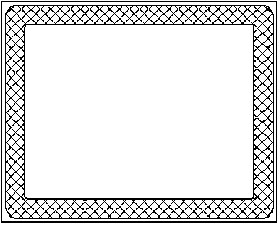
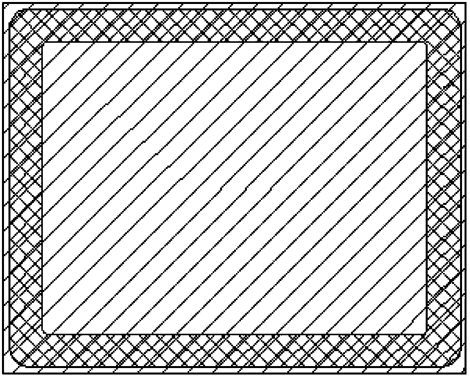
[0058] There is a frame on the substrate glass of the touch base layer. The frame is made of black or white photoresist. There are several rows of the same X-row ITO film conductive electrodes in the frame. The X-row ITO film conductive electrodes are composed of IM-ITO (Index match The abbreviation of ITO...


PUM


Abstract

The invention discloses a capacitive touch screen. The capacitive touch screen comprises a touch-control basic layer and an induction basic layer, wherein the side, provided with X lines of ITO film conductive electrodes, of the touch-control basic layer is attached to the back side, provided with Y lines of conductive electrodes, of the induction basic layer face to face through optical transparent adhesive. The capacitive touch screen is of a G1M structure, wherein G refers to a glass sensor and serves as a carrier of the touch-control basic layer, 1M is a PET film sensor with a metal mesh which is low in wire resistance and low in sheet resistance printed on the surface and serves as a carrier of the induction basic layer, and the 1M is attached to the G to prevent film explosion. The capacitive touch screen has the advantages that the manufacturing is simple and cost is low. The capacitive touch screen is the best choice among capacitive touch screens with large sizes and middle sizes and particularly with sizes larger than 7 inches for a user.

Description

technical field [0001] The invention relates to the technical field of touch screens, in particular to a structure of a medium-sized and large-sized capacitive touch screen, and a process for producing the medium-sized and large-sized capacitive touch screen. Background technique [0002] In today's society, electronic products with capacitive touch screens as the human-machine interface are becoming more and more popular. Due to the visual enjoyment and convenient use, consumers are more and more fond of medium and large-sized touch screen products. From large-screen mobile phones, PADs to ultrabook computers, multi-touch capacitive touch screens are used more and more widely, and their sizes are also getting larger. [0003] Capacitive touch screen Capacity Touch Panel (CTP) works by using the current induction of the human body. It is a touch screen that senses touch signals through the combination of electrodes and human body characteristics. When the four sides of the ...

Claims


Application Information

Patent Timeline
Patent Type & Authority Applications(China)
IPC IPC(8): G06F3/044
Inventor 陈奇沈励许沭华迟晓晖李建勇
Owner WUHU TOKEN SCI
Why Eureka
Try Eureka